Plate vacuum sucking device and method thereof for hoisting plate

A suction device and vacuum suction cup technology, which is applied in transportation and packaging, object supply, pile separation, etc., can solve the problems of high surface quality requirements for adsorption plates, inability to absorb plates, and lack of automatic cleaning functions, etc.

Active Publication Date: 2014-05-14
SUZHOU JUHUIBANG NEW MATERIAL TECH CO LTD
View PDF5 Cites 26 Cited by
  • Summary
  • Abstract
  • Description
  • Claims
  • Application Information

AI Technical Summary

Problems solved by technology

[0003] (1) The surface quality of the adsorption plate is high, and it does not have an automatic cleaning function. When there is dust, iron filings and other sundries on the surface of the plate, it needs to be manually cleaned before it can be absorbed;
[0004] (2) For a vacuum suction cup feeding device that uses a centralized suction device, each suction cup is connected to the suction device through a branch, if a suction cup leaks, it will cause the entire suction cup system to leak, resulting in all the suction cups being damaged. Can not absorb the plate;
[0005] (3) When absorbing plates, it often happens that two or more plates are absorbed at a time, which seriously affects subsequent processing

Method used


Image

  • Plate vacuum sucking device and method thereof for hoisting plate
  • Plate vacuum sucking device and method thereof for hoisting plate
  • Plate vacuum sucking device and method thereof for hoisting plate

Examples


Embodiment Construction

[0031] Specific embodiments of the present invention will be described in detail below in conjunction with the accompanying drawings.

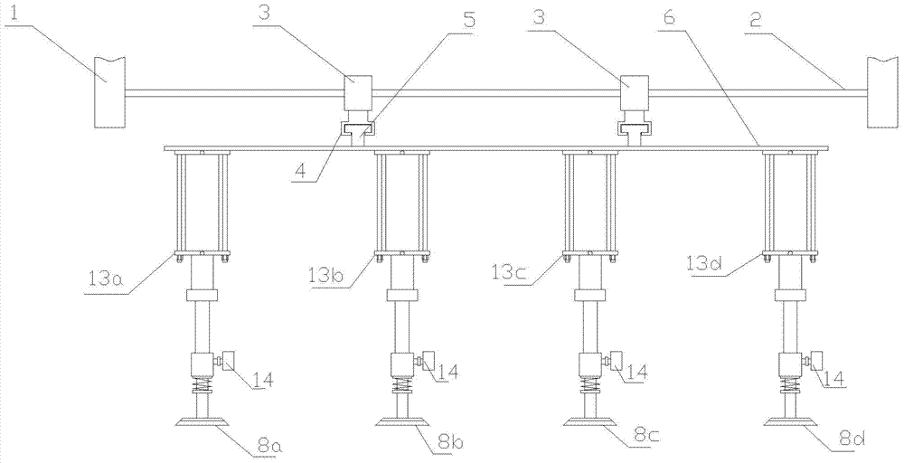
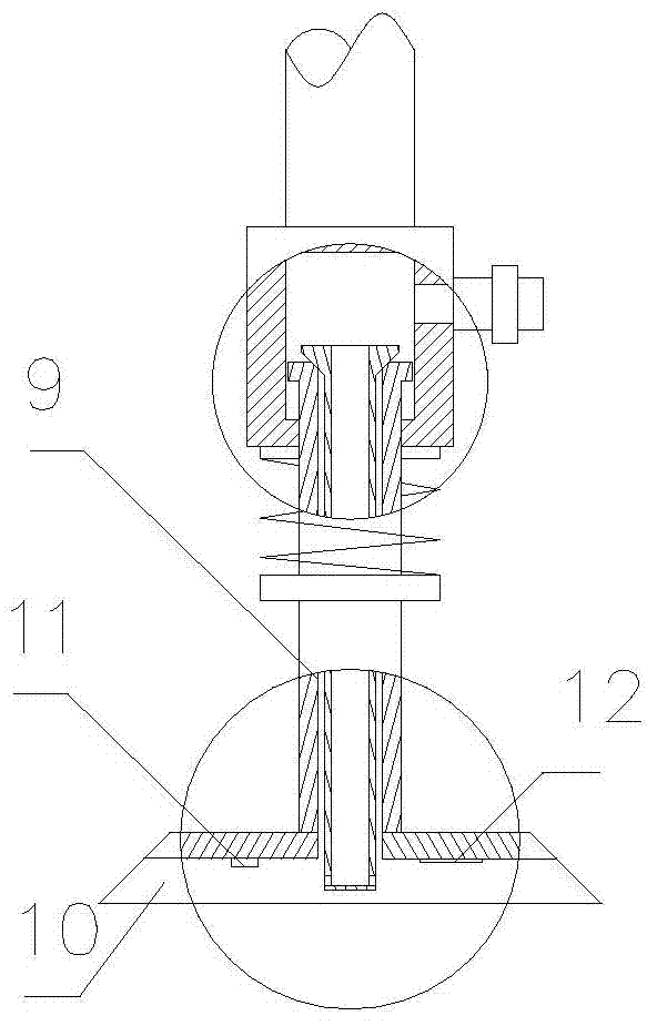
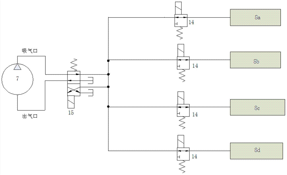
[0032] Such as Figure 1-3 As shown, a plate vacuum suction device includes a PLC (not shown in the figure) and a conveying guide rail 2 arranged on a frame 1, a conveying slider 3 is stuck on the conveying guide rail 2, and a conveying slider 3 is provided on the lower surface of the conveying slider 3. There is an adjustment guide rail 4, an adjustment slider 5 is stuck on the adjustment guide rail 4, and an installation base 6 is arranged on the bottom of the adjustment slider 5. The bottom surface of the installation base 6 is vertically arranged in parallel with four columns of hydraulic cylinders 13a, 13b, 13c, 13d controlled by PLC. , 8c, 8d. The vacuum suction cups 8a, 8b, 8c, 8d include a suction cup mount 9 connected to the bottom of the piston rod of the hydraulic cylinder, the suction cup mount 9 is provided with a gas channel, a...


PUM


Abstract

The invention discloses a vacuum sucking device capable of effectively sucking a plate under the situation that the surface cleanliness of the plate is not high. The vacuum sucking device comprises a PLC and an installation base which is movably arranged on a machine frame, a plurality of vacuum suction cups are movably arranged on the lower surface of the installation base, the vacuum suction cups on the peripheries of two sides of the installation base are vertically driven by at least one hydraulic cylinder controlled by the PLC, the rest of the vacuum suction cups are vertically driven by at least one hydraulic cylinder controlled by the PLC, a vacuum pump controlled by the PLC is arranged on the machine frame, an air outlet and an air inlet of the vacuum pump are communicated with an electromagnetic directional valve controlled by the PLC, an outlet of the electromagnetic directional valve is communicated with the vacuum suction cups through pipelines, and the inner surface of the suction cup body of each vacuum suction cup is provided with a vacuum pressure sensor and a jetting proximity switch connected with the PLC.

Description

technical field [0001] The invention relates to a board vacuum suction device and a method for hoisting boards. Background technique [0002] The plate vacuum suction control system is a commonly used feeding device on the modern flexible automatic plate machining production line. . At present, the vacuum extraction methods of the plate vacuum suction device are mainly divided into two types. One is to use a vacuum pump or a large vacuum tank to evacuate all the suction cups, that is, to provide a single vacuum source, which is connected to each suction cup through the air pipeline; the other It uses a cylinder piston or a small vacuum tank to vacuumize the suction cups one by one, that is, each suction cup is connected to a set of cylinder piston device or a small vacuum tank, and the suction cup is vacuumed by pushing and pulling the piston through a mechanical device. The suction cup devices of these two vacuuming methods have been widely used in manufacturing now, but ...

Claims


Application Information

Patent Timeline
Patent Type & Authority Applications(China)
IPC IPC(8): B65H5/08
Inventor 沈滨张磊张建李钦奉王明禄
Owner SUZHOU JUHUIBANG NEW MATERIAL TECH CO LTD
Why Eureka
Try Eureka