
A movable support

A technology of moving support frame and moving frame, applied in the direction of transmission, transmission parts, belt/chain/gear, etc., can solve problems such as damage to threaded transmission mechanism, reduce distance, reduce deflection, and improve working accuracy and reliability. Effect

Active Publication Date: 2015-12-30
徐州志旺新能源有限公司
View PDF5 Cites 0 Cited by
  • Summary
  • Abstract
  • Description
  • Claims
  • Application Information

AI Technical Summary

Problems solved by technology

[0003] For this special linear conveying occasion, the length of the screw is required to be relatively long. When the moving frame with the nut moves to one end of the screw, the distance between the corresponding support points on the screw is relatively far, and the screw forms a certain angle relative to the axis under its own gravity. Deflection, when the drive motor drives the screw to rotate at high speed through the coupling, the screw will swing in the circumferential direction and generate alternating loads on the support point, which will easily lead to damage to the screw transmission mechanism

Method used


Image

  • A movable support

Examples


Embodiment Construction

[0018] The present invention will be further described below in conjunction with the accompanying drawings.

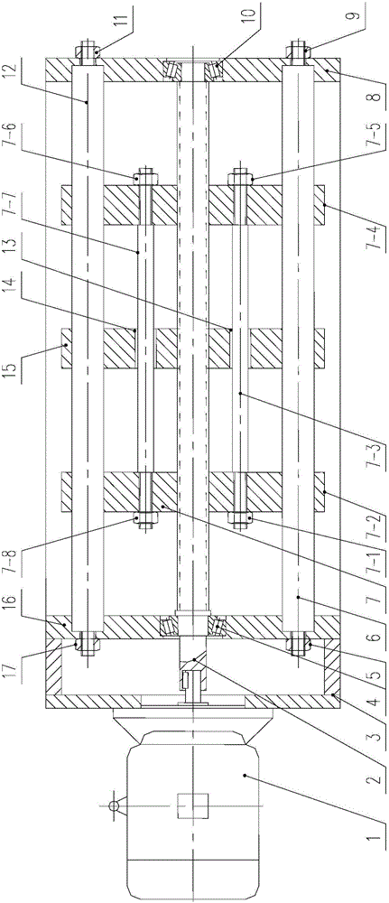
[0019] Such as figure 1 As shown, a movable support frame includes: a driving motor 1, a screw rod 2, a frame 3, a lower guide rod 6, an upper guide rod 12, a working mobile frame 15, and a mobile support frame 7.

[0020] Drive motor 1 is installed on the left end of frame 3, and its output shaft is connected with the left end of screw rod 2, and drive motor 1 can drive screw rod 2 to realize rotation, and transmits power; There are frame left vertical plate 16 and frame on frame 3 Right vertical plate 8, bearing hole is set respectively on the frame left vertical plate 16 and the frame right vertical plate 8, and left bearing 4 and right bearing 10 are installed respectively; Screw rod 2 is installed on the frame left vertical plate 16 and the frame right Between the vertical plates 8, the left and right parts are respectively supported by the left bearing 4 and the...


PUM


Abstract

The invention discloses a movable supporting frame comprising a drive motor, a threaded rod, a rack, a lower guide rod, an upper guide rod, a working movable frame and movable supporting frame bodies. On the occasions with high-precise threaded transmission and long-distance linear conveying, the number of supporting points of the threaded rod is increased, the maximum distance between every two supporting points is greatly reduced, the bending resistant capacity of the threaded rod is improved, the deflection formed relative to the axis of the threaded rod is reduced, alternating loads generated by high-speed rotation of the threaded rod are reduced, and working precision and reliability of a threaded transmission mechanism are improved.

Description

technical field [0001] The invention relates to a movable support frame, in particular to a movable support frame for a screw rod in a thread transmission, and belongs to the field of electrical and electromechanical technology. Background technique [0002] At present, thread transmission has been widely used in linear conveying and transmission mechanisms, especially the development and promotion of ball screw mechanism, which greatly improves the accuracy of thread transmission and makes the application field of thread transmission more extensive. Generally, the screw drive mechanism mainly consists of a drive motor, a frame, a guide column, a coupling, a screw, and a moving frame with nuts. Its basic working principle is: the rotation of the drive motor drives the screw to rotate through the coupling, and pushes the moving frame with the nut. Under the guidance of the guide column, it moves linearly along the axis of the screw to change the rotation direction of the driv...

Claims


Application Information

Patent Timeline
Patent Type & Authority Patents(China)
IPC IPC(8): F16H57/023
CPCF16H25/2015F16H2025/2081
Inventor 钱雪松郑子宁钱子凡
Owner 徐州志旺新能源有限公司
Learn More