Multi-beam laser condensation transmission device

A transmission device and laser technology, applied in the direction of condenser, light guide, optics, etc., can solve the problems of high manufacturing cost, inability to meet engineering needs, poor focusing effect of multiple laser beams, etc., and achieve the effect of low cost, simple structure and easy molding.

Inactive Publication Date: 2014-05-14
SHAANXI NORMAL UNIV
View PDF6 Cites 5 Cited by
  • Summary
  • Abstract
  • Description
  • Claims
  • Application Information

AI Technical Summary

Problems solved by technology

However, its manufacturing cost is high, especially for the poor focusing effect of multiple laser beams, which cannot meet the actual engineering needs

Method used


Image

  • Multi-beam laser condensation transmission device
  • Multi-beam laser condensation transmission device
  • Multi-beam laser condensation transmission device

Examples


Embodiment 1

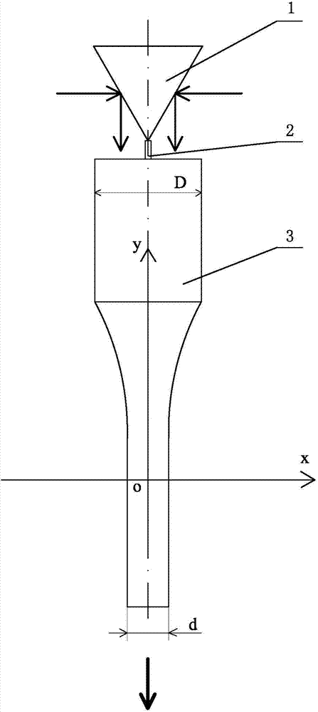
[0016] exist figure 1 Among them, the multi-beam laser focusing and transmitting device of this embodiment is composed of a reflective pyramid 1, a pillar 2, and a laser transmitting and focusing rod 3 connected together.

[0017] The cone tip of reflective pyramid 1 is bonded to the central position of support 2 with optical glue, and the other end of support 2 is bonded to the central position of the light incident end face of laser transmission focusing rod 3 with optical glue, and the centerline of the cone of reflective pyramid 1 Coinciding with the center line of the laser transmission focusing rod 3, the reflective pyramid 1 is made of crown glass (H-K9). The reflective pyramid 1 in this embodiment is a regular quadrilateral pyramid, and the apex angle of each side of the regular quadrangular pyramid is 45°. The side of the reflective pyramid 1 is a laser reflective surface, and the side is coated with an aluminum reflective film. The reflective pyramid 1 is used to ref...

Embodiment 2

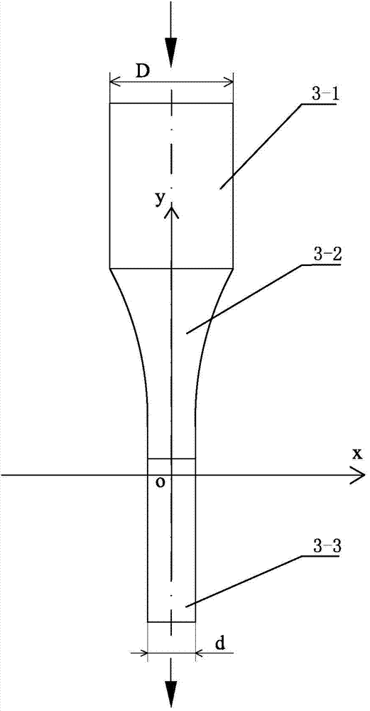
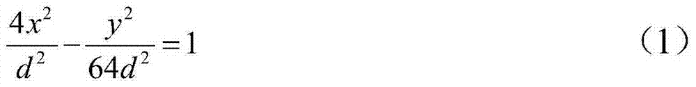
[0023] The geometric shape of the laser transmission focusing rod 3 in this embodiment is as follows: the light incident end of the light focusing section 3-2 is connected as a whole to form a laser transmission section 3-1, and the light emitting end of the light focusing section 3-2 is connected as a whole to form a The optical adjustment section 3-3 constitutes a laser transmission hyperbolic focusing rod, the geometric shape of the laser transmission section 3-1 is a cylinder with a diameter D of 10.5mm, and the geometric shape of the optical adjustment section 3-3 is a cylinder with a diameter d of 1.5mm Cylinder, that is, D is equal to 7d, and the geometric shape of the light-focusing section 3-2 is a body of revolution whose side is a hyperboloid. The y-axis is the hyperbolic surface of revolution formed by the rotation of the central axis, and the hyperbolic equation is the same as the hyperbolic equation (1) of embodiment 1. In the hyperbolic equation, x is the radius ...

Embodiment 3

[0025] The geometric shape of the laser transmission focusing rod 3 in this embodiment is as follows: the light incident end of the light focusing section 3-2 is connected as a whole to form a laser transmission section 3-1, and the light emitting end of the light focusing section 3-2 is connected as a whole to form a whole. Optical section 3-3 constitutes a laser transmission hyperbolic focusing rod, the geometric shape of laser transmission section 3-1 is a cylinder with a diameter D of 15mm, and the geometric shape of the whole light section 3-3 is a cylinder with a diameter d of 1.5mm , that is, D is equal to 10d, and the geometric shape of the light-concentrating section 3-2 is a body of revolution with a hyperbolic surface on the side. It is the hyperbolic surface of revolution formed by the rotation of the central axis, and the hyperbolic equation is the same as the hyperbolic equation (1) of embodiment 1. In the hyperbolic equation, x is the radius variable of the light...


PUM


Abstract

The invention relates to a multi-beam laser condensation transmission device. A conical tip of a reflection pyramid is arranged at the central position of a supporting column, the other end of the supporting column is arranged at the central position of a light incidence end face of a laser transmission condensation bar, and the central line of the reflection pyramid coincides with the central line of the laser transmission condensation bar. With regard to laser beams entering the lateral surface of the reflection pyramid, a plurality of laser beams entering the input end face of the laser transmission condensation bar perpendicularly are reflected by the reflection pyramid, enter a condensation section through a laser transmission section, is transmitted along the central line of the condensation section straightly, and enters a light shaping section through the condensation section; other light enters a hyperboloid of the lateral surface of the condensation section to form total reflection, is transmitted to the output end of the condensation section in a broken line mode formed by multiple total reflection, is gathered to the output end of the condensation section with small divergence angles, and then enters the light shaping section; therefore, light energy concentration of the multiple laser beams during transmission is achieved. The multi-beam laser condensation transmission device has the advantage of being simple in structure, small in size, low in cost, high in condensation efficiency and the like.

Description

technical field [0001] The invention belongs to the technical field of laser transmission equipment or devices, and in particular relates to an optical device for transmitting and converging multiple beams of laser light on the same optical device. Background technique [0002] Focusing of laser beams is one of the key technologies in laser applications. The quality of the laser beam focusing effect has an important impact on the utilization efficiency of laser energy. Traditional laser beam focusing methods are divided into transmissive focusing methods using ordinary spherical lenses as focusing elements and reflective focusing methods using different mirrors as focusing elements. At the same time, it is difficult to couple with the optical fiber, which affects its application range. The self-focusing rod lens invented in the 1960s, due to its unique optical characteristics and the characteristics of perfect combination with semiconductor lasers and optical fibers, is us...

Claims


Application Information

Patent Timeline
Patent Type & Authority Applications(China)
IPC IPC(8): G02B19/00G02B17/06G02B6/00
Inventor 张宗权苗润才黄育红王文成姚志刘志存鲁百佐杨宗立
Owner SHAANXI NORMAL UNIV
Why Eureka
Try Eureka