
Clock recovery method and device for transmitting EI signals based on Ethernet

A clock recovery and Ethernet technology, applied in the field of communication and information system network transmission, can solve the problems of packet drop, wander, time variation, etc., achieve good wander performance indicators, smooth missing teeth, and reduce phase wander.

Active Publication Date: 2014-05-14
HUAXIAO PRECISION SUZHOU
View PDF2 Cites 4 Cited by
  • Summary
  • Abstract
  • Description
  • Claims
  • Application Information

AI Technical Summary

Problems solved by technology

However, the disadvantage of the clock phase detector used in the PLL is that the resolution can only reach one bit. When the recovered clock is very close to the actual value, it takes a long time for the phase difference to accumulate to one bit, which will cause drift , it is difficult to meet the requirements of roaming specifications
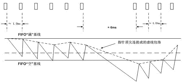
In addition, due to the characteristics of Ethernet, the time when data packets arrive at the destination will vary randomly, and may even drop packets.
In addition, the packet data is a large block burst data. When a packet arrives, it is hundreds or even thousands of bytes. The change of the write pointer of the elastic memory is jumpy. In this case, the phase change detection filter cannot be changed from The detection of pointer difference is done by general low-pass filtering method

Method used


Image

  • Clock recovery method and device for transmitting EI signals based on Ethernet
  • Clock recovery method and device for transmitting EI signals based on Ethernet

Examples


Embodiment Construction

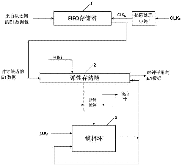
[0023] A clock recovery method based on Ethernet to transmit E1 signal, the method includes the following steps in sequence: (1) First level coarse adjustment: clock CLK H The missing tooth clock CLK is obtained after the trapping process G , Store the E1 data packet from the Ethernet into the FIFO memory 1 buffer, and use the missing tooth clock CLK G For reading, FIFO memory 1 outputs the E1 data of the clock lacking teeth; (2) The second level of fine adjustment: store the E1 data of the clock lacking teeth into the elastic memory 2, the missing teeth clock CLK G As the input of the phase-locked loop 3, the phase-locked loop 3 outputs a synchronization signal to the elastic memory 2, and the output of the phase-locked loop 3 is used as its feedback input. The phase-locked loop 3 controls the elastic memory 2 by monitoring the difference between read and write pointers. The output clock frequency, if the difference between the read and write pointers is greater than the set valu...


PUM


Abstract

The invention relates to a clock recovery method for transmitting EI signals based on the Ethernet. The clock recovery method includes the steps that an EI data package coming from the Ethernet is stored in an FIFO memorizer and buffered, the data package is read through a tooth missing clock CLKG, and EI data of clock tooth missing are output by the FIFO memorizer; the EI data of clock tooth missing are stored in an elastic memorizer, a phase-locked loop outputs synchronizing signals to the elastic memorizer, meanwhile output of the phase-locked loop is input as feedback, the phase-locked loop controls the output clock frequency of the elastic memorizer by monitoring difference between a reading pointer and a writing pointer of the elastic memorizer, if the difference between the reading pointer and the writing pointer is larger than a set value, the clock frequency of the output of the phase-locked loop is reduced, otherwise, the clock frequency of the output of the phase-locked loop is increased, and the elastic memorizer outputs the EI data with clock smoothed. The invention further discloses a clock recovery device for transmitting the EI signals based on the Ethernet. A clock is recovered with two-level buffering adjustment to reduce phase position diffuse movement, smooth missed teeth and recover the clock meeting the related ITU-TG. 823 requirements; a good diffuse movement performance index can be achieved without changing a frame structure.

Description

Technical field [0001] The invention relates to the technical field of communication and information system network transmission, in particular to a method and device for clock recovery based on Ethernet to transmit E1 signals. [0002] Background technique [0003] In the new generation of IP-based communication network, in order to achieve multi-service transmission, at the sending end, the real-time service (TDM) is packaged to make it into the data packet of the Ethernet packet, and then transmitted; at the receiving end, for recovery In the original TDM service, data was counted and jitter removed, so as to obtain the timing information of the code stream. Since in the TDMoIP system, the signal that needs to be sent at the sender is a standard E1 signal, in order to transmit in the Ethernet, the E1 signal is split and encapsulated to turn it into a fixed-size Ethernet packet, the original E1 signal All the timing information in the signal is lost. The signal received at the ...

Claims


Application Information

Patent Timeline
IPC IPC(8): H04L7/033
Inventor 杨福锦徐钊刘景超杨震斌方成郭颖郑纪玲
Owner HUAXIAO PRECISION SUZHOU
Learn More