Integrated and distributed type stitching control display system based on network

A technology for controlling display and integration, which is applied in CCTV systems, components of TV systems, components of color TVs, etc. Good compatibility, cost-effective products, and the effect of solving cost and space problems

Active Publication Date: 2014-05-14
上海晨驭信息科技有限公司
View PDF10 Cites 11 Cited by
  • Summary
  • Abstract
  • Description
  • Claims
  • Application Information

AI Technical Summary

Problems solved by technology

This kind of structure is not based on the network. The engineering construction is limited by the transmission length of the video cable, so it can only be placed close to the large screen, and because the heat is too concentrated, a fan must be added, which reduces the stability of the system.
[0006] Patent CN 1026100869 A and patent CN203151670 U, the essence of which is one patent, is a typical distributed splicing controller in the traditional sense, one input node supports one input source, one output node supports one single screen, this distributed controller architecture Simple, stable and reliable, low power consumption, but in actual construction, due to the many and distributed network cables, the construction difficulty is not lower than that of the centralized architecture, and the biggest problem is the high cost; while the echo screen only supports a single screen, which means When there are more than 64 large screens, the images on the screen are basically unclear

Method used


Image

  • Integrated and distributed type stitching control display system based on network
  • Integrated and distributed type stitching control display system based on network
  • Integrated and distributed type stitching control display system based on network

Examples


Embodiment Construction

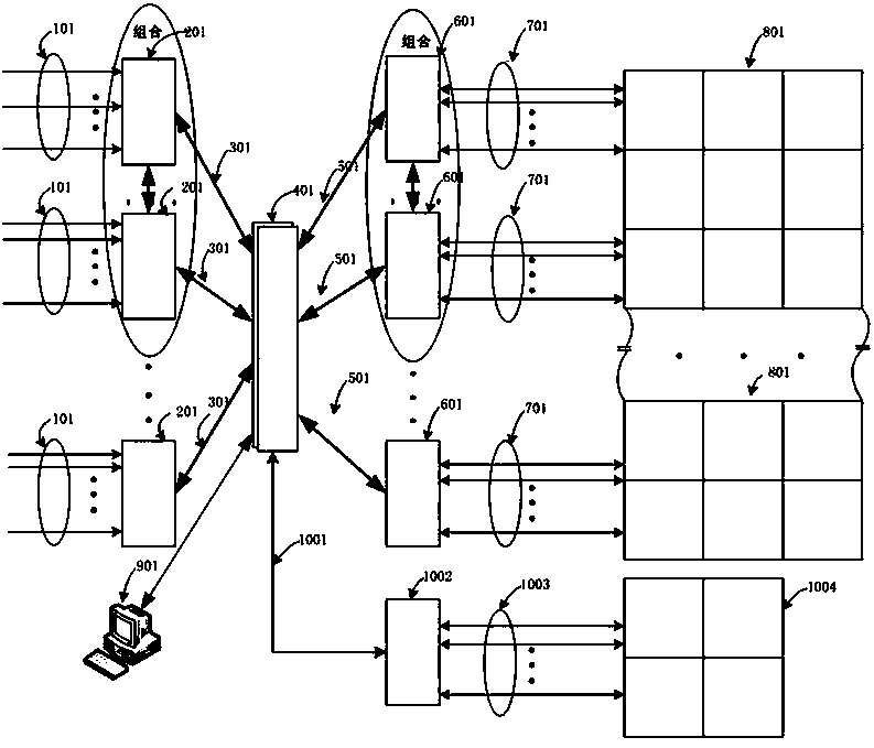
[0023] The topological diagram of the whole system of the present invention is as figure 1 As shown, the system includes the following network elements: video input interface unit 101, video acquisition and preprocessing unit 201, input video packet transmission interface unit 301, network switching routing unit 401, output video packet transmission unit 501, first video stitching Post-processing unit 601, video display signal transmission interface unit 701, a*b large-screen splicing screen 801, main control unit 901, echo transmission unit 1001, second video splicing post-processing unit 1002, echo transmission interface unit 1003 and The splicing screen 1004 is echoed by c*d. Several video acquisition and pre-processing units 201 are combined to form several video acquisition and pre-processing sets; several first video splicing post-processing units 601 form several first video splicing post-processing sets; several second video splicing post-processing units 1002 Form se...


PUM


Abstract

The invention discloses an integrated and distributed type stitching control display system based on a network. The integrated and distributed type stitching control display system based on the network comprises an input device, at least one network switch routing unit, at least one master control unit and an output device. The master control unit is connected with each network switch routing unit. The network switch routing units are connected with a plurality of video collecting and preprocessing units through input video packet transmitting interface units in the input device and connected with a plurality of first video stitching post-processing units through output video packet transmitting units in the output device, and therefore a stellate network structure or a chain network structure is formed. By the adoption of the integrated and distributed type stitching control display system based on the network, the problems concerning the cost and the space of distributed type transmission can be effectively solved, and a series of problems that when integrated type transmission is adopted, the transmission distance is short, installation is inflexible, heat dissipation is difficult, the noise of a fan is high, windowing is limited, and front-end investment is high in the process of expansion are solved; in this way, a product developed based on a method of integrated and distributed type stitching control display system is high in cost performance and quite good in backward compatibility.

Description

technical field [0001] The invention relates to an image splicing controller, more specifically a novel image splicing system that combines centralized and distributed images. Background technique [0002] The large-screen splicing display system is more and more widely used in traffic command, weather monitoring, TV display, communication, military, security and other fields. At present, there are various splicing controls on the market, but they can be summarized as follows: 1. Based on the PC architecture splicing controller, this kind of splicing controller has very high power consumption, unstable image display, and high cost; 2. Based on Backplane switching technology, a splicing controller that uses DSP and FPGA for image processing, this type of controller has a cost advantage in the selected appropriate scale, but it lacks engineering flexibility and can only be placed close to the splicing screen , if the number of splicing screens is large, due to the limitation ...

Claims


Application Information

Patent Timeline
Patent Type & Authority Applications(China)
IPC IPC(8): H04N7/18H04N5/265
Inventor 潘卫明
Owner 上海晨驭信息科技有限公司
Why Eureka
Try Eureka