Deaerator system and method for deaeration

A control system, bubble technology, applied in degasser systems and in the field of degassing, to achieve the effect of improving energy efficiency

Inactive Publication Date: 2014-05-14
TETRA LAVAL HLDG & FINANCE SA
View PDF5 Cites 2 Cited by
  • Summary
  • Abstract
  • Description
  • Claims
  • Application Information

AI Technical Summary

Problems solved by technology

This method of degassing is highly efficient, but in an era of rising energy costs and awareness of energy conservation, there is still room for improvement

Method used


Image

  • Deaerator system and method for deaeration
  • Deaerator system and method for deaeration
  • Deaerator system and method for deaeration

Examples


Embodiment Construction

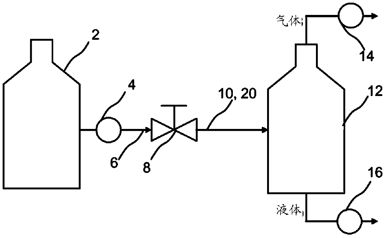
[0026] will refer to figure 1 Portions of a system for handling liquids are described. The invention may form part of such a system, but individual components may be replaced without departing from the scope of the invention as defined by the claims.

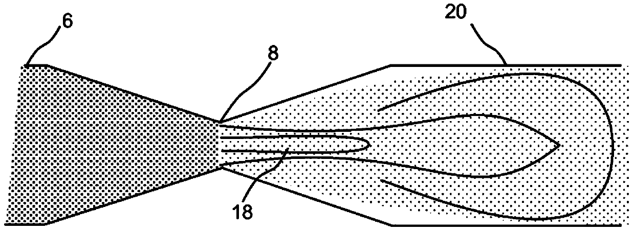
[0027] From an upstream location, the system includes a storage tank 2 or other system for containing or conveying the liquid to be treated. The system also includes a pump 4 for raising the pressure of the liquid so that the liquid is subjected to an elevated static pressure P 上游 , in order to force it to flow downstream. Pump 4 may in one or more embodiments be a centrifugal pump, however other alternatives are also possible. Conduit 6 leads the liquid to the first processing step, ie to nucleation valve 8 . Before describing the details of the valve, a few words should be said about the arrangement downstream of the valve. A line 10 leading the liquid after the nucleation valve 8 opens into a separation vessel 12 . In t...


PUM

PropertyMeasurementUnit
Lengthaaaaaaaaaa
Diameteraaaaaaaaaa

Abstract

In a method for deaerating a liquid the liquid is pressurized to a pressure above atmospheric, after which it is guided to an upstream end of a nucleation valve. A low pressure resides on the downstream end of the nucleation valve and as the liquid passes the valve, bubble nucleation is initiated, forming the first step in a deaeration process. According to the method the temperature and pressure on the downstream side of the valve is controlled such that the static pressure is above the saturation pressure, while the lowest pressure as the liquid passes the valve is below or equal to the saturation pressure.

Description

technical field [0001] The present invention relates to a system and method for degassing liquid food. Background technique [0002] In the field of packaging liquid products, degassing is a well-established concept and in most processing plants, for example, liquid products are received in bulk at the first end of the line and at the other end of the line In plants that are delivered in individual packaging containers, degassing is incorporated as an essential step. Air (or oxygen) may be present in a liquid product for a number of different reasons, two of the main reasons being that the air (or oxygen) is dispersed or dissolved. In the case of milk, there will be some oxygen present in the milk before it leaves the cow, and more oxygen will be mixed and dissolved into the milk at each processing step from the milking process itself. [0003] Air and oxygen can cause several negative effects ranging from: reduced skimming efficiency in separators, cavitation in product d...

Claims


Application Information

Patent Timeline
IPC IPC(8): B01D19/00
CPCB01D19/0063B01D19/0036A01J11/04A23C1/12
Inventor 弗雷德里克·因宁斯托马斯·斯科格隆
Owner TETRA LAVAL HLDG & FINANCE SA
Why Eureka
Try Eureka