
Device for placing extensible inner support in ureter

A technology of internal stent and ureter, which is applied in the field of medical devices, can solve the problems of changing the anti-reflux mechanism of ureter, aggravating the degree of hydronephrosis in the kidney, and restricting the daily life of patients, so as to avoid the occurrence of pyelonephritis and the symptoms of hydronephrosis The effect of aggravating and simple structure

Inactive Publication Date: 2014-05-21
THE FIRST AFFILIATED HOSPITAL OF HENAN UNIV OF SCI & TECH
View PDF5 Cites 0 Cited by
  • Summary
  • Abstract
  • Description
  • Claims
  • Application Information

AI Technical Summary

Problems solved by technology

One of the methods to treat the ureter is to place an internal stent at the stenosis of the ureter. The existing technology is mainly to implant a guide wire into the ureter through a cystoscope or ureteroscope, and push the double "J"-shaped ureteral stent along the guide wire. , the upper end of which is inserted into the lower end of the renal pelvis and placed in the bladder, the operation process is cumbersome, and due to the two-way permeability of the double "J" ureteral stent after the operation, the normal anti-reflux mechanism of the ureter is changed. High or the position of the bladder is higher than the kidneys when the patient is in the supine position, which can also cause the urine in the bladder to reflux into the renal pelvis, cause pyelonephritis or aggravate the degree of hydrops in the kidneys, seriously affect the surgical effect, and limit the daily life of the patient

Method used


Image

  • Device for placing extensible inner support in ureter
  • Device for placing extensible inner support in ureter
  • Device for placing extensible inner support in ureter

Examples


Embodiment Construction

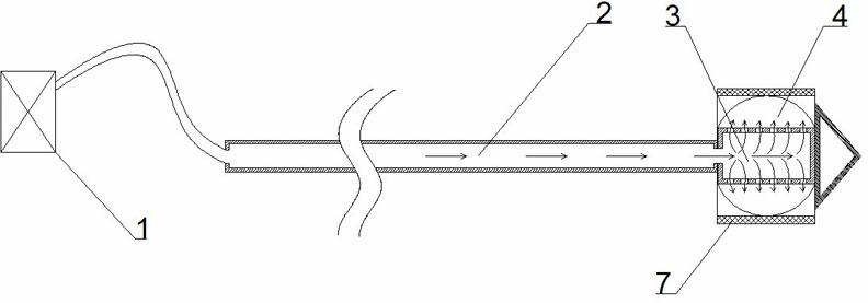
[0014] As shown in the figure: a device for placing a retractable ureteral stent, including an air source 1, a sheath tube 2, a stoma tube 3, an elastic spherical membrane 4 and an advancing tip 5, and the side wall of the stoma tube 3 is provided with A plurality of ventilation holes 6, both ends of the sheath tube 2 are provided with openings, one end opening of the sheath tube 2 is connected to the gas source 1 through a pipeline, and one end opening of the sheath tube 2 communicates with the inner cavity of the stomata tube 3, the The end of the stomata tube 3 away from the sheath tube 2 is connected to the forward end 5, the elastic spherical membrane 4 is sleeved outside the stomata tube 3, and the connection between the elastic spherical membrane 4 and the stomata tube 3 is a sealed connection. The advancing head 5 has a conical cylindrical structure, and the conical tip of the advancing head 5 is set facing away from the stomata tube 3 . The advancing tip 5 of this str...


PUM


Abstract

The invention relates to a device for placing an extensible inner support in the ureter. The device for placing the extensible inner support in the ureter comprises an air source, a sheath, a porous tube, an elastic ball membrane and an advancing end. A plurality of vent holes are formed in the side wall of the porous tube. The two ends of the sheath are respectively provided with an opening. The opening at one end of the sheath is connected with the air source through a pipeline. The opening at the other end of the sheath is communicated with an inner cavity of the porous tube. The end, far away from the sheath, of the porous tube is connected with the advancing end. The porous tube is sleeved with the elastic ball membrane. The elastic ball membrane is connected with the porous tube in a sealing mode. According to the device for placing the extensible inner support in the ureter, the structure is simple, the inner support can be placed at the narrow position of the ureter, the whole placing process is simple and rapid, the success rate of an operation is high, the normal backflow-resistant mechanism of the ureter is not changed, the situation that urine in the bladder flows back into the pelvis can be avoided, nephropyelitis and exacerbation of hydronephrosis symptoms can be avoided, the pain of a patient is relieved, and the quality of life of the patient is improved.

Description

technical field [0001] The invention relates to the technical field of medical instruments, in particular to a placement device for a retractable ureteral stent. Background technique [0002] In clinical medicine, ureteral stenosis refers to the narrowing of the ureteral lumen due to various reasons. Although the continuity of the lumen has not been interrupted, it has caused varying degrees of upper urinary tract obstruction and hydronephrosis. In addition to congenital causes, inflammation, injury and surgical scars are the main causes. One of the methods to treat the ureter is to place an internal stent at the stenosis of the ureter. The existing technology is mainly to implant a guide wire into the ureter through a cystoscope or ureteroscope, and push the double "J"-shaped ureteral stent along the guide wire. , the upper end of which is inserted into the lower end of the renal pelvis and placed in the bladder, the operation process is cumbersome, and due to the two-way...

Claims


Application Information

Patent Timeline
Patent Type & Authority Applications(China)
IPC IPC(8): A61F2/95
Inventor 李志军时振国朱小娟
Owner THE FIRST AFFILIATED HOSPITAL OF HENAN UNIV OF SCI & TECH
Learn More