
Drilling equipment for bearing

A drilling equipment and bearing technology, applied in the field of bearing processing, can solve the problems of low degree of automation, slow drilling speed, low work efficiency, etc., and achieve the effects of high work efficiency, easy production and simple structure

Active Publication Date: 2014-05-21
ZHEJIANG LIZU MACHINERY
View PDF9 Cites 17 Cited by
  • Summary
  • Abstract
  • Description
  • Claims
  • Application Information

AI Technical Summary

Problems solved by technology

[0002] The inner ring and outer ring of the bearing are generally called rings. During processing, in order to meet the needs of lubrication, it is often necessary to open through holes on the outer circumferential surface of the rings. The number of through holes can be one or two. According to It needs to be confirmed that it communicates with the groove on the inner surface to ensure that there is enough lubricating oil in the groove when the bearing is working. Therefore, the position of this hole has precision requirements. At present, many holes drilled in the inner and outer rings of bearings are Drilling with a bench drill manually, the accuracy is not high, and the efficiency is low. The patent application publication number application number: CN201320187258.8 application date: 2013-04-15 Chinese utility model discloses a bearing ring drilling device, including installation plate, a suspension device for suspending the drilled bearing ring, and a bolt device for positioning the bearing ring after being inserted into the drilled hole after the bearing ring is drilled and rotated at an included angle a. The utility model bearing ring drilling device can ensure that the bearing ring will not be deformed during processing
However, it still has shortcomings: the degree of automation is relatively low, and the whole process is still manually operated; the drilling speed is slow and the work efficiency is relatively low

Method used


Image

  • Drilling equipment for bearing
  • Drilling equipment for bearing
  • Drilling equipment for bearing

Examples


Embodiment Construction

[0038] The following descriptions are only preferred embodiments of the present invention, and do not limit the scope of the present invention.

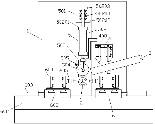
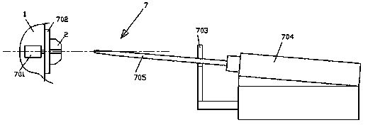
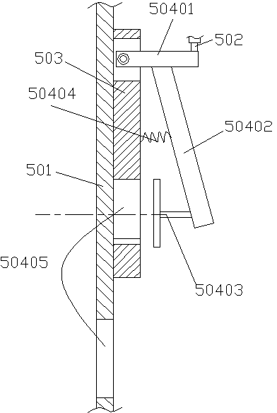
[0039] Examples, see attached figure 1 , 2, 3, 4, 5, drilling equipment for bearings, including machine tool body 1, tensioning spindle 2 installed on machine tool body 1, machine tool body including bed, electrical control part, transmission part, tensioning spindle control part etc., the tensioning spindle 2 can be radially expanded and retracted to realize the tensioning and fixing of the ferrule. When it is placed for drilling, the ferrule will rotate or move axially. The structure it adopts can be similar to three The jaw chuck can be controlled by pneumatic control, electric control or mechanical transmission. When it is opened, the outer circular surface forms an opening, because the main body of the machine tool and the tensioning spindle are well-known technologies in the art, and will not be described in detail here.

[0...


PUM


Abstract

The invention discloses drilling equipment for a bearing. The drilling equipment for the bearing comprises a machine tool body and an expanding main shaft mounted on the machine tool body, and further comprises a feeding device, a material putting device, a conveying and press-in device, a drilling device and a discharging device. The feeding device is used for containing and conveying a plurality of rings to be drilled. The material putting device is located above the feeding device and used for putting one ring on the feeding device into the conveying and press-in device at a time. The conveying and press-in device is used for conveying the rings put by the material putting device to the position of the expanding main shaft, the rings are mounted on the expanding main shaft in a sleeved mode, and the rings are fixed through the expanding main shaft. The drilling device is used for carrying out drilling on the rings fixed on the expanding main shaft. The discharging device is used for at least separating the rings with drilling finished from the expanding main shaft. The drilling equipment for the bearing is simple in structure, easy to manufacture, high in working efficiency and good in drilling effect.

Description

technical field [0001] The invention relates to the technical field of bearing processing, and more specifically relates to a drilling device for bearing inner and outer rings. Background technique [0002] The inner ring and outer ring of the bearing are generally called rings. During processing, in order to meet the needs of lubrication, it is often necessary to open through holes on the outer circumferential surface of the rings. The number of through holes can be one or two. According to It needs to be confirmed that it communicates with the groove on the inner surface to ensure that there is enough lubricating oil in the groove when the bearing is working. Therefore, the position of this hole has precision requirements. At present, many holes drilled in the inner and outer rings of bearings are Drilling with a bench drill manually, the accuracy is not high, and the efficiency is low. The patent application publication number application number: CN201320187258.8 applicat...

Claims


Application Information

Patent Timeline
IPC IPC(8): B23B41/00B23Q7/00
CPCB23B41/00B23B2215/12B23Q7/00
Inventor 詹明强
Owner ZHEJIANG LIZU MACHINERY
Learn More