Rotary shaft feedback detection hydraulic locking system

A feedback detection and locking system technology, applied in the direction of positioning devices, large fixed members, measuring/indicating equipment, etc., can solve the problem that the position of the cabinet cannot be adjusted and corrected in time, the position of the cabinet cannot be effectively identified and fed back, and cannot meet the requirements High-precision polyhedron processing requirements and other issues, to achieve the effect of simple and reliable fixing method, simple structure, and large locking torque

Active Publication Date: 2016-06-08
陈小青 +1
View PDF6 Cites 0 Cited by
  • Summary
  • Abstract
  • Description
  • Claims
  • Application Information

AI Technical Summary

Problems solved by technology

[0004] The present invention mainly provides a rotating shaft feedback detection hydraulic locking system with large locking torque, high positioning accuracy, and accurate identification and feedback of the position of the box fitted on the rotating shaft. The positioning accuracy of the cabinet on the board is low, and the position of the cabinet cannot be effectively identified and fed back, resulting in the inability to adjust and correct the position of the cabinet in time, thus failing to meet the technical problems of high-precision polyhedron processing requirements, etc.

Method used


Image

  • Rotary shaft feedback detection hydraulic locking system
  • Rotary shaft feedback detection hydraulic locking system

Examples


Embodiment

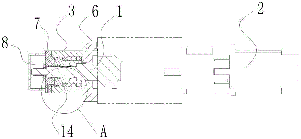
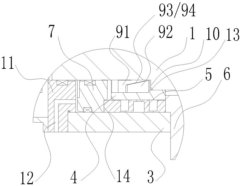
[0018] Such as figure 1 and figure 2 As shown, a rotary shaft feedback detection hydraulic locking system of the present invention includes a mandrel 1 and a servo motor 2 coaxially connected to the right end of the mandrel 1 through a coupling sleeve. The box body 6 of the blank, the left end of the mandrel 1 is coaxially sleeved with a cylinder body 3, the inner end of the cylinder body 3 is fixed on the box body 6, and the corresponding mandrel 1 in the cylinder body 3 is tightened by conical expansion A ring-shaped wear-resistant sleeve 4 is fixed in the mechanism suit, and the conical expansion mechanism includes an inner split ring 91 and an outer split ring 92 that are matched with each other. It is embedded in the middle hole of the wear-resistant sleeve 4. One end of the inner split ring 91 opposite to the outer split ring 92 has an outer tapered surface 93, and one end of the outer split ring 92 opposite to the outer split ring 93 has an inner ring. The tapered s...


PUM


Abstract

The invention discloses a rotating shaft feedback detection hydraulic locking system, provides a locking system with large locking torque, high positioning accuracy, and can accurately identify and feedback the position of the box body, and solves the problem of box body positioning accuracy in the prior art Low, the position of the cabinet cannot be adjusted and corrected and other technical problems. It includes a mandrel and a servo motor connected to one end of the mandrel. The middle part of the mandrel rotates and connects to the box. The other end of the mandrel opposite to the servo motor is sleeved with a cylinder connected to the box. The corresponding core in the cylinder A wear-resistant sleeve is fixed on the shaft, and the wear-resistant sleeve is covered with a corrugated sleeve. The inner end of the corrugated sleeve is connected to the box body, and the outer end extends to the outside of the wear-resistant sleeve, and is slidably connected to the mandrel corresponding to the outer end of the corrugated sleeve. There is a piston, the piston is driven by the power unit and pushes the corrugated sleeve inwards to compress it so that the cylinder body is tightened and fixed on the wear-resistant sleeve, and an encoder that can automatically identify the position of the box relative to the mandrel is installed on the mandrel. The controller is connected to the servo motor through the control system.

Description

technical field [0001] The present invention relates to a rotating shaft locking system, in particular to a rotating shaft that can automatically and accurately lock a box set on a rotating shaft, automatically detect the position of the box, and feed back the detected position information to a servo motor in time for adjusting the rotating shaft Feedback detection hydraulic locking system. Background technique [0002] Some parts often need to be precisely fixed on the rotating shaft to be processed, such as the equipment for precision grinding polyhedron, the box used to fix the polyhedron blank in the equipment needs to be precisely positioned on the rotating shaft, and then the rotating shaft drives the box and The polyhedron blank on the box is turned, but there is no special stop mechanism in the existing processing equipment. Generally, the stop is realized by the self-locking force between the worm gear and the worm in the equipment, but due to the existence of a cer...

Claims


Application Information

Patent Timeline
Patent Type & Authority Patents(China)
IPC IPC(8): B23Q15/22B23Q17/22B23Q3/12
CPCB23Q1/26B23Q17/00B24B41/06B24B47/12
Inventor 郭晋秦黄永生郑永黄金星
Owner 陈小青
Why Eureka
Try Eureka