Method used for detecting welding quality of welding carried out in intermediate layer connection manner

A connection method and welding quality technology, applied in the direction of using sonic/ultrasonic/infrasonic waves to analyze solids, etc., can solve a large number of problems, and achieve the effect of improving detection efficiency, simplifying detection operation process, and reducing detection time.

Active Publication Date: 2014-05-21
GRIKIN ADVANCED MATERIALS
View PDF9 Cites 7 Cited by
  • Summary
  • Abstract
  • Description
  • Claims
  • Application Information

AI Technical Summary

Problems solved by technology

However, if the company has a wide variety of products, it means that a large number of comparison test blocks a

Method used


Image

  • Method used for detecting welding quality of welding carried out in intermediate layer connection manner
  • Method used for detecting welding quality of welding carried out in intermediate layer connection manner
  • Method used for detecting welding quality of welding carried out in intermediate layer connection manner

Examples


Embodiment 1

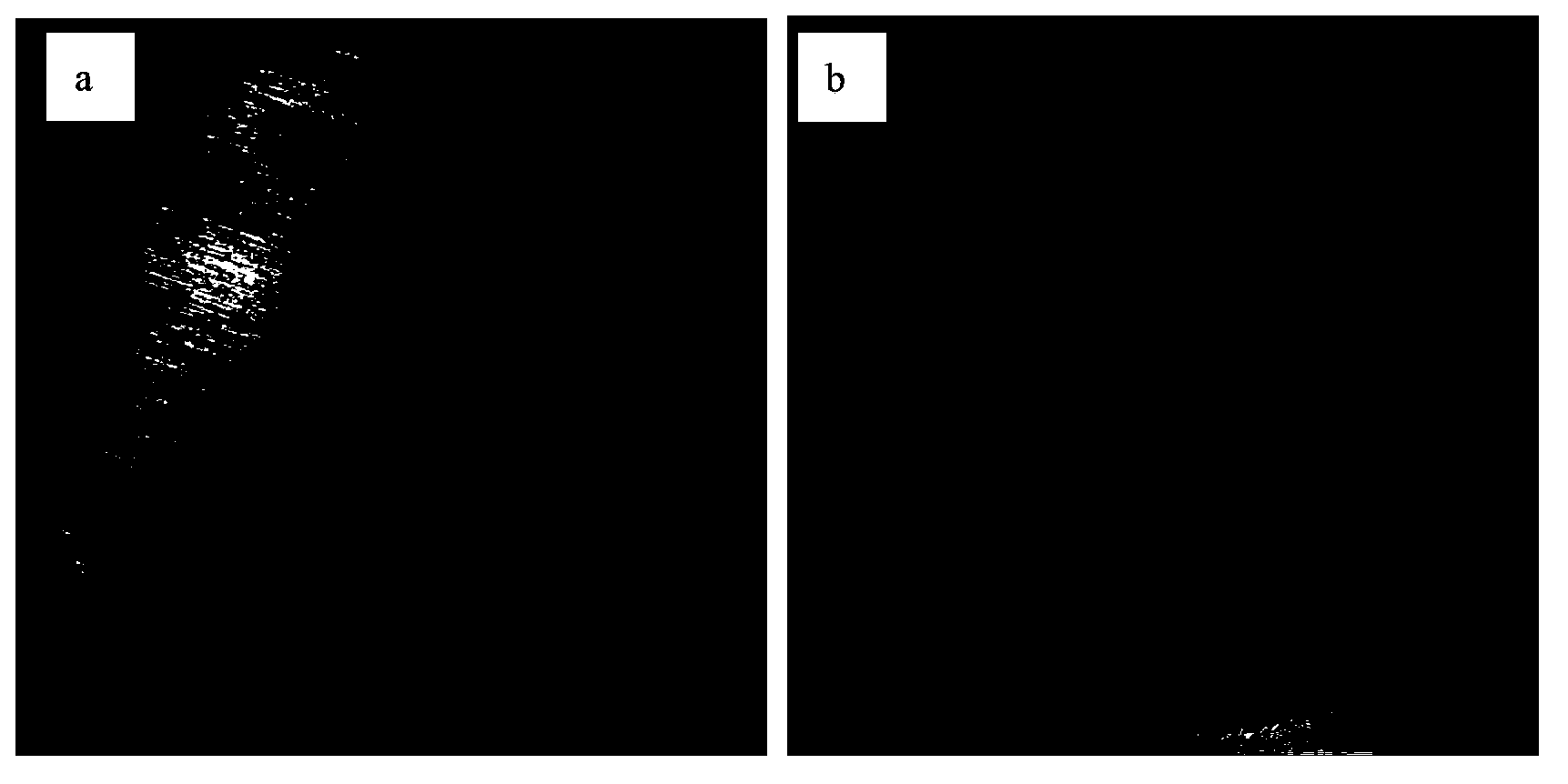
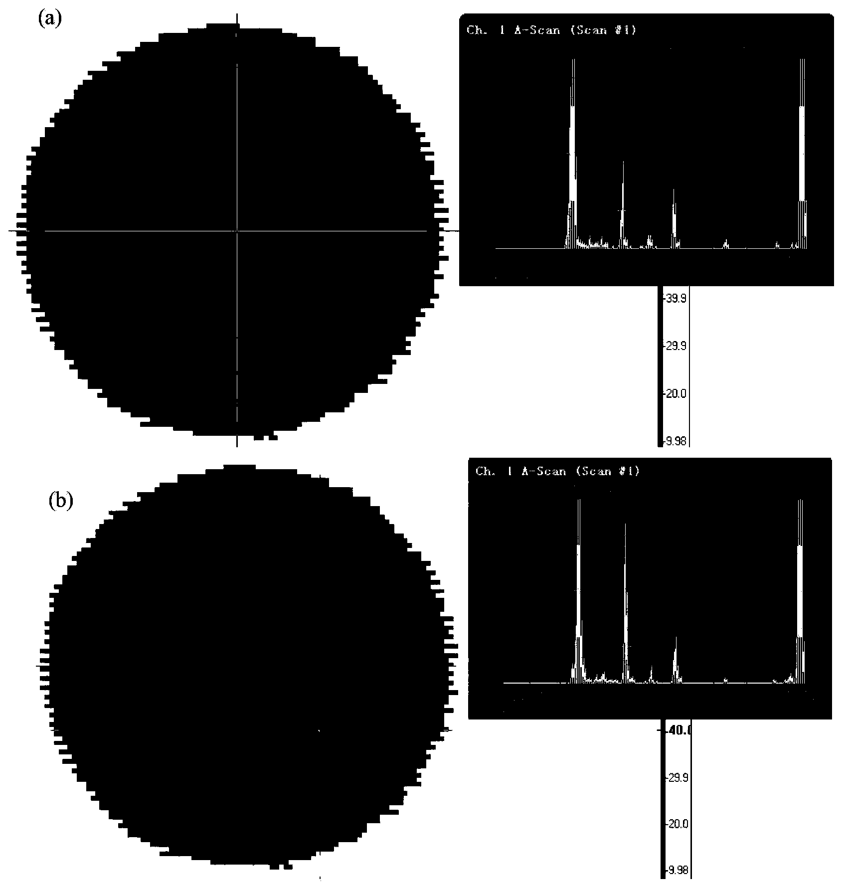
[0024] Clean Al-Cu indium welding comparison test block ( figure 1 a, b) The surface is oily, so that the roughness of the detection surface is ≤6.4μm; then select the water immersion focusing probe, and the frequency of the probe is 10MHz. In A-scan mode, adjust the incident angle of the probe so that the probe is incident vertically on the water layer. Keep the sensitivity unchanged, move along different axes on the detection surface, find the complete welding area with the lowest echo amplitude, adjust the gain value so that the echo height of the welding interface is 50% of the full screen; then the gain value at this time is the scan Check the sensitivity. Put the electronic gate on the welding interface wave, and set the height of the gate to 20% of the full screen. Determine the scanning area, use ultrasonic longitudinal wave pulse reflection to scan, and form an ultrasonic C-scan image. It can be seen that the echo amplitude in the welded area is 50%. figure 2 a, ...

Embodiment 2

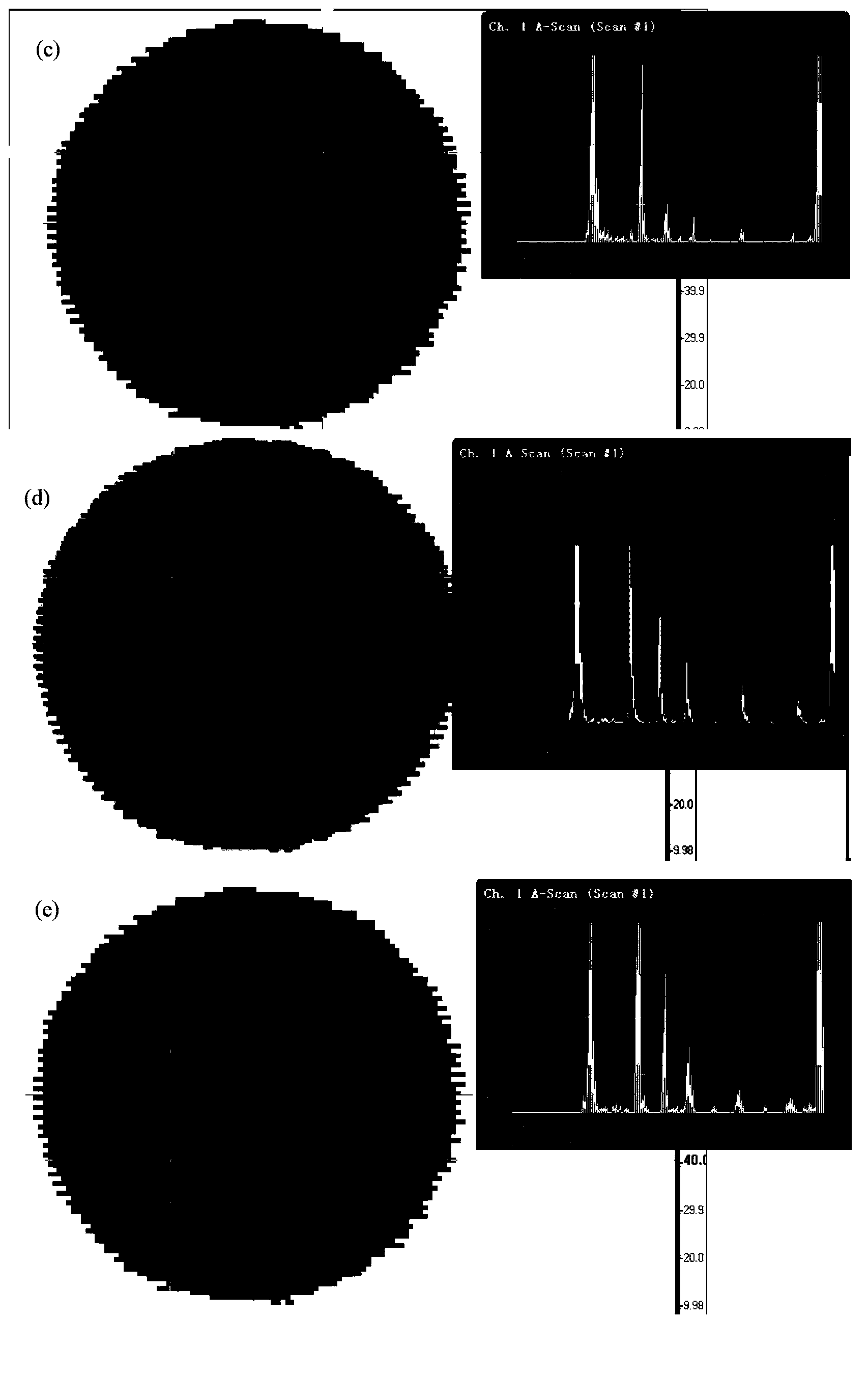
[0027] For the actual ITO ceramic plate and oxygen-free copper plate indium welding welding workpiece (such as image 3 ) detection. Clean the oil on the surface of the workpiece, and then select a water immersion focusing probe with a frequency of 25MHz. In A-scan mode, adjust the incident angle of the probe so that the probe is incident vertically on the water layer. Keep the sensitivity unchanged, move along different axes on the detection surface, find the complete welding area with the lowest echo amplitude, adjust the gain value so that the echo height of the welding interface is 50% of the full screen; then the gain value at this time is the scan Check the sensitivity. Put the electronic gate on the welding interface wave, and set the height of the gate to 30% of the full screen. Determine the scanning area, use ultrasonic longitudinal wave continuous reflection to scan, and form an ultrasonic C-scan image. Ultrasonic images from the Cu-In interface ( Figure 4 ) a...


PUM


Abstract

The invention belongs to the field of nondestructive testing ultrasonic flaw detection, and discloses a method used for detecting welding quality of welding which is carried out in an intermediate layer connection manner. According to the method, ultrasonic longitudinal wave reflection type liquid immersion technology is adopted; a focus is focused on a connection interface, sensitivity is maintained unchanged; a scanning mechanism is moved along different axial directions on a detecting surface; echo wave amplitudes of the connection interface are observed; a welding complete zone with a lowest echo wave amplitude is found; sensitivity is adjusted to a value that the echo wave amplitude of the welding complete zone accounts for 45 to 55% of full screen amplitude; scanning on a whole workpiece is carried out with the sensitivity value; and calculation and evaluation on the workpiece are carried out based on a defect determination criterion, wherein according to the defect determination criterion, the echo wave amplitude of the connection interface is more than 80% of the full screen amplitude. No extra reference test piece is needed by the method; detection cost is reduced greatly; ultrasonic detection processes are simplified; detection time is saved; and detection efficiency is increased.

Description

technical field [0001] The invention belongs to the technical field of non-destructive testing ultrasonic flaw detection, and in particular relates to a method for testing the welding quality of welding using an intermediate layer connection mode. Background technique [0002] Welding technology is an operation method that uses welding materials (welding rods or wires) to connect two or more base materials (workpieces to be welded) into a whole under high temperature or high pressure conditions. Welding methods are divided into three categories: fusion welding, pressure welding and brazing. The welding method using the middle layer connection belongs to brazing. During the welding process, there are some discontinuities in the welding area that degrade the performance of the joint area, such as cracks, slag inclusions, oxide inclusions, wrinkles, metal inclusions, holes, lack of welding, lack of fusion, incomplete penetration, undercut, burning These discontinuities are col...

Claims


Application Information

Patent Timeline
IPC IPC(8): G01N29/04
Inventor 刘红宾陈明任仁于海洋徐学礼何金江熊晓东吕保国江轩
Owner GRIKIN ADVANCED MATERIALS
Why Eureka
Try Eureka