Supercharge Your Innovation With Domain-Expert AI Agents!

Electrowetting display unit and method for manufacturing thereof

A technology of electrowetting display and manufacturing method, which is applied in chemical instruments and methods, optical components, photolithography process exposure devices, etc., can solve the problems of small differences in hydrophilic and hydrophobic properties, and the inability to further reduce the thickness of electrowetting displays, etc.

Active Publication Date: 2014-05-21
IND TECH RES INST
View PDF5 Cites 11 Cited by
  • Summary
  • Abstract
  • Description
  • Claims
  • Application Information

AI Technical Summary

Problems solved by technology
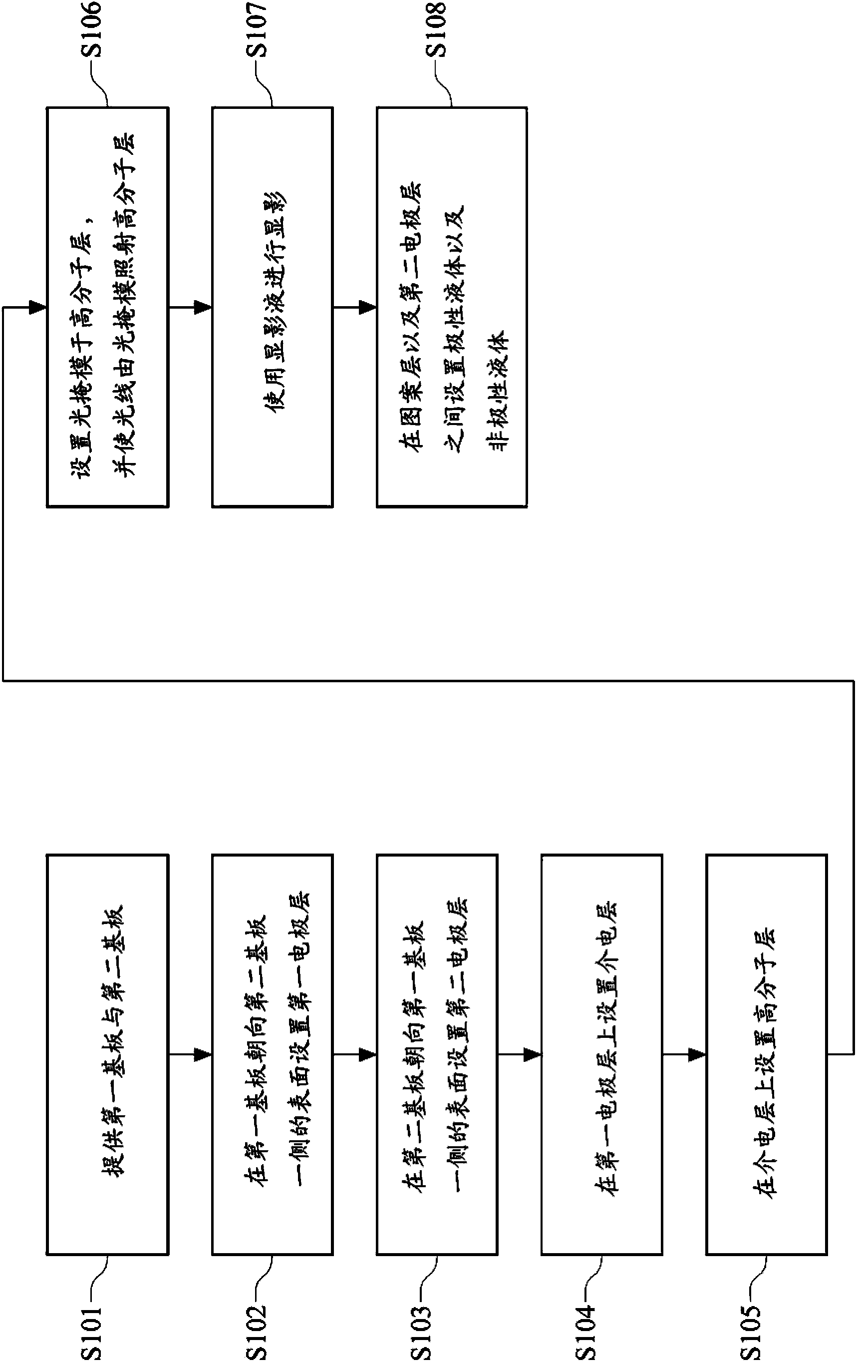
[0007] The present application relates to an electrowetting display component and its manufacturing method, so as to solve the problems in the prior art that the difference in hydrophilic and hydrophobic properties between the hydrophobic insulating layer and the hydrophilic barrier is small and the thickness of the electrowetting display cannot be further reduced

Method used


Image

  • Electrowetting display unit and method for manufacturing thereof
  • Electrowetting display unit and method for manufacturing thereof
  • Electrowetting display unit and method for manufacturing thereof

Examples


Embodiment 1

[0045] First, put 100g of isopropyl alcohol (Isopropyl Alcohol, IPA) into a round bottom bottle, and then put 1.0g of (3-aminopropyl) triethoxysilane ((3-aminopropyl) triethoxysilane) (Aldrich) into Stir into a round bottom bottle. Next, take out 5 g of the above mixed solution and put it into another round bottom bottle, and then add 0.2 g of vinyl-terminated polydimethylsiloxane (Mw=6,000) (product code: Gelest DMS- V21) and 7 mg of platinum (II) acetylacetonate (platinum (II) acetylacetonate) (Aldrich). Wherein, the vinyl-terminated polydimethylsiloxane is an organosiloxane with a Si-H bond, and the photocrosslinkable group is a vinyl group with a carbon-carbon double bond. The above mixed solution was stirred at room temperature for 1 hour, and then the mixed solution was coated on the substrate by spin coating, wherein the rotation rate of the spin coating was 3000 rpm (rotation per minute, rpm) and the coating time was 20 seconds . Next, set a photomask above the subs...

Embodiment 2

[0048] First, put 100g of isopropyl alcohol (Isopropyl Alcohol, IPA) into a round bottom bottle, and then put 1.0g of (3-aminopropyl) triethoxysilane ((3-aminopropyl) triethoxysilane) (Aldrich) into Stir into a round bottom bottle. Next, take out 5 g of the above mixed solution and put it into another round bottom bottle, then add 0.2 g of vinyl-terminated polydimethylsiloxane (vinyl-terminated polydimethylsiloxane) (Mw=17,200) (product number: Gelest DMS- V25) and 7 mg of platinum(II) acetylacetonate (platinum(II) acetylacetonate) (Aldrich). Wherein, the vinyl-terminated polydimethylsiloxane is an organosiloxane with a Si-H bond, and the photocrosslinkable group is a vinyl group with a carbon-carbon double bond. The above mixed solution was stirred at room temperature for 1 hour, and then the mixed solution was coated on the substrate by spin coating, wherein the spin rate of the spin coating was 3000 rpm and the coating time was 20 seconds. Next, set a photomask above the ...


PUM


Abstract

The invention relates to an electrowetting display unit and method for manufacturing thereof. The method for manufacturing an electrowetting display unit includes the following steps. A first substrate and a second substrate are provided. A first conductive layer is disposed on one side of the first substrate. A second conductive layer is disposed on one side of the second substrate. A polymer layer, which includes a siloxane containing a light-induced cross linkable group and a Si-H bond, is disposed on the first conductive layer. The molecular weight of the monomer of the siloxane is equal to or greater than 5000. A part of the polymer layer is exposed to a light so as to form a plurality of hydrophobic sections. A hydrophilic section is developed by treating a developing agent. The hydrophilic section and the plurality of hydrophobic sections form a pattern layer together. Polar liquid and non-polar liquid are disposed between the pattern layer and the second conductive layer.

Description

technical field [0001] The present application relates to a display component and a manufacturing method thereof, in particular to an electrowetting display component and a manufacturing method thereof. Background technique [0002] Since Robert A.Hayes and B.J.Feenstra of Philips disclosed the earliest electrowetting display in the journal Nature in 2003, related research is developing vigorously due to the simple structure and simple materials of the electrowetting display. [0003] Generally speaking, the structure of an electrowetting display mainly includes polar liquid, hydrophobic ink, hydrophobic insulating layer, hydrophilic barrier and transparent electrode. Between the contact angle, to achieve the purpose of color conversion. [0004] When no voltage is applied to the electrowetting display, the polar liquid and the surface of the hydrophobic insulating layer repel each other, so that the hydrophobic ink is covered by the polar liquid and presents a flat state. ...

Claims


Application Information

Patent Timeline
IPC IPC(8): G02B26/02C09K23/00
CPCG03F7/0035G02B26/005G02B2207/115G03F7/20
Inventor 刘怡君郭书玮陈品诚
Owner IND TECH RES INST
Features
  • R&D
  • Intellectual Property
  • Life Sciences
  • Materials
  • Tech Scout
  • Unparalleled Data Quality
  • Higher Quality Content
  • 60% Fewer Hallucinations
Learn More