
Method of assembling an ultrasonic transducer and the transducer obtained thereby

A transducer, ultrasonic technology, applied in the use of vibration fluid, manufacture/assembly of piezoelectric/electrostrictive devices, piezoelectric/electrostrictive/magnetostrictive devices, etc.

Inactive Publication Date: 2014-05-21
RENAULT SA
View PDF16 Cites 3 Cited by
  • Summary
  • Abstract
  • Description
  • Claims
  • Application Information

AI Technical Summary

Problems solved by technology

[0011] In the case of this combined brazing paste, the brazing temperature can be reduced to around 300°C, but the problem of depolarization of these ceramic components still remains

Method used


Image

  • Method of assembling an ultrasonic transducer and the transducer obtained thereby
  • Method of assembling an ultrasonic transducer and the transducer obtained thereby
  • Method of assembling an ultrasonic transducer and the transducer obtained thereby

Examples


Embodiment Construction

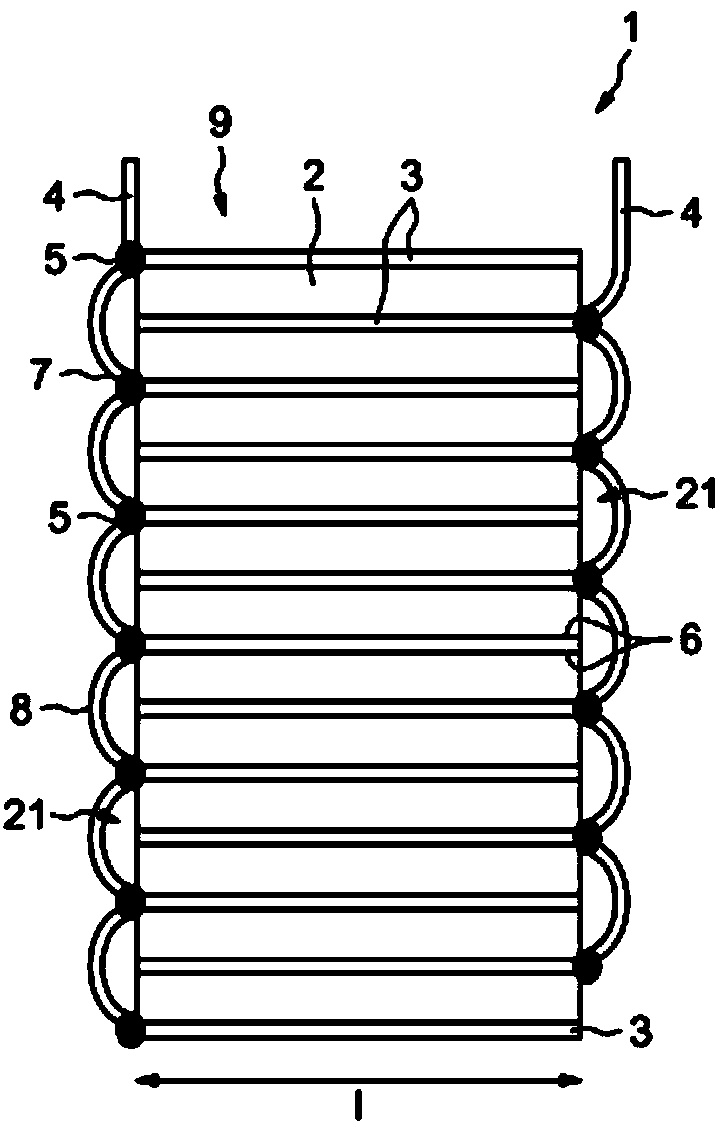
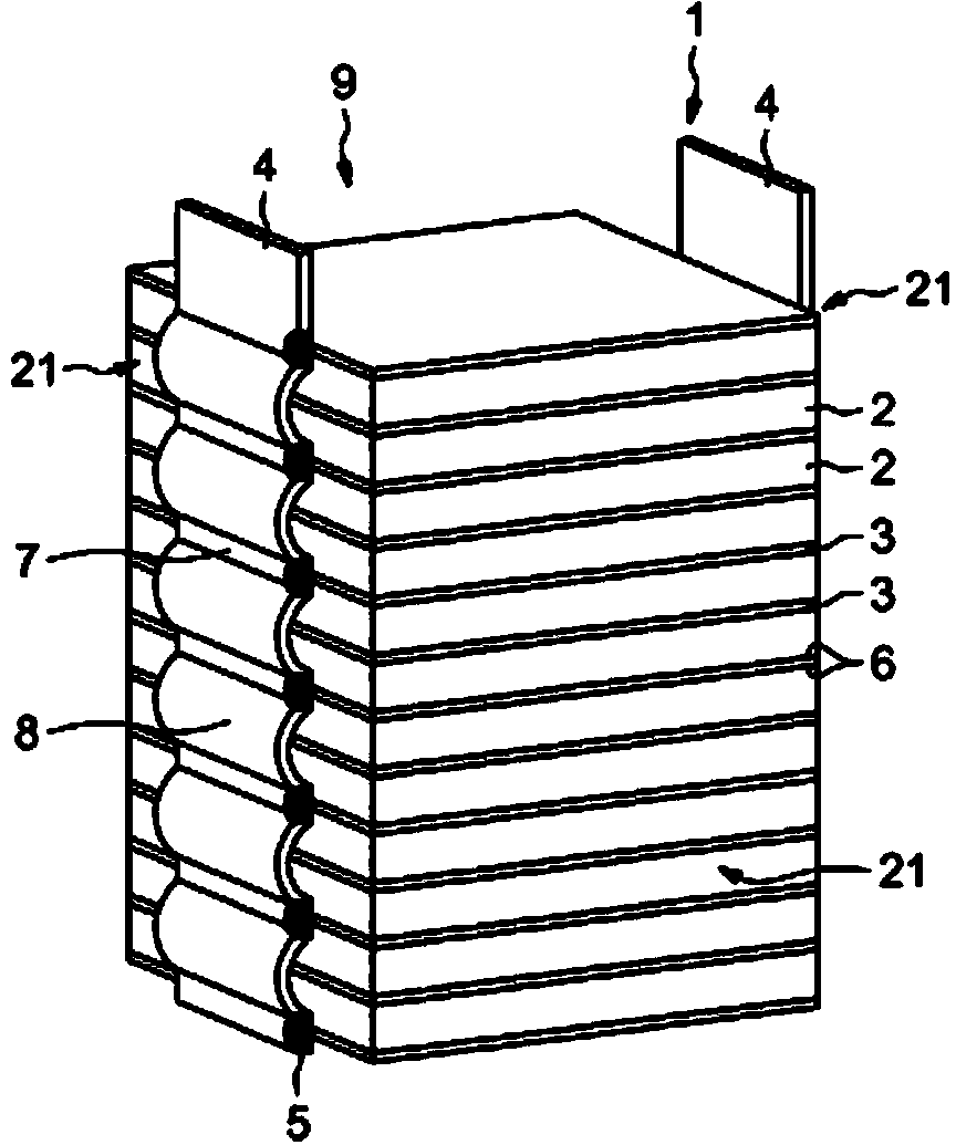
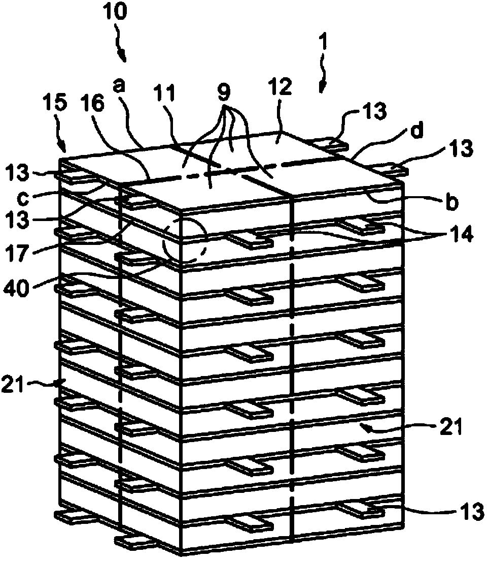
[0041] figure 1 is a schematic diagram of a transducer according to the invention. The transducer 1 comprises a plurality of ceramic wafers 2 , for example piezoelectric ceramic wafers, which alternate with a plurality of electrodes 3 . At the interfaces of the ceramics 2 and the electrodes 3 are arranged thin connection layers 6 which are typically between 10 and 50 microns and preferably between 10 and 30 microns in thickness. The electrodes are cut from rolled metal sheets, for example from sheets of annealed silver or copper beryllium alloy, or even from sheets of titanium alloy. The thickness of each intermediate electrode is greater than 20 microns, and preferably between 50 microns and 1 mm.

[0042] The thickness of these substantially rectangular or square profile wafer form ceramics is typically between 1 mm and 5 mm to be able to operate within the stress and frequency ranges required to produce a fuel injector. The width "1" of the stack 9 comprising alternating...


PUM

PropertyMeasurementUnit
Sizeaaaaaaaaaa
Average temperatureaaaaaaaaaa

Abstract

An ultrasonic transducer comprises a stack (9) of multiple flat electrodes (3) between which are interposed ceramic wafers (2) of substantially the same surface area as the electrodes (3), the stacked contours of the ceramic wafers and electrode wafers defining substantially flat or cylindrical side faces (21) of the stack. The method of manufacturing this transducer comprises the following steps: a ceramic wafer (2) and an electrode wafer (3) are alternately stacked, placing between each ceramic wafer and its two neighbouring electrodes a composition (6) of which at least 75% by weight, and preferably at least 80% by weight, is comprised of silver nanoparticles having a grain size of smaller than or equal to 80 nanometres, and preferably of smaller than or equal to 60 nanometres; and the stack is compressed by heating to a temperature of less than or equal to 280 DEG C, and preferably of between 200 DEG C and 250 DEG C.

Description

technical field [0001] The subject of the invention is a piezoelectric or magnetostrictive transducer, in particular suitable for operation at ultrasonic frequencies. [0002] More specifically, the subject of the invention is a transducer that can be used as an actuator for a fuel injector of a heat engine. Background technique [0003] These fuel injectors using such ultrasonic actuators are described, for example, in patent applications FR2941746, FR2936025, FR2936024, FR2918123, FR2889257. Such injectors make it possible to inject fuel very finely and to optimize combustion in direct injection engines. [0004] Such an improvement in spraying makes it possible in particular to limit the amount of particles emitted by the vehicle. [0005] An ultrasonic transducer typically consists of a stack in which a piezoelectric ceramic layer is "sandwiched" between two electrodes at a time, connected to two different terminals of a power source. The working range (frequency, tra...

Claims


Application Information

Patent Timeline
IPC IPC(8): H01L41/083H01L41/22H01L41/047
CPCB06B1/0611H10N30/871H10N30/872H10N30/877H10N30/057H10N30/067H10N30/50
Inventor L·勒万G·格雷卡
Owner RENAULT SA
Learn More