
Hydraulic jack

A hydraulic jack and jack technology, applied in the field of hydraulic jacks, can solve problems such as unfavorable safety and stability of hydraulic jacks, shortening the service life of hydraulic oil, easy leakage of hydraulic oil, etc. ability, the effect of ensuring security and stability

Inactive Publication Date: 2014-05-28
HENAN UNIV OF SCI & TECH
View PDF6 Cites 2 Cited by
  • Summary
  • Abstract
  • Description
  • Claims
  • Application Information

AI Technical Summary

Problems solved by technology

[0002] The jack is one of the most widely used lifting equipment. The jack is divided into mechanical and hydraulic. Compared with the mechanical jack, the hydraulic jack has a larger lifting capacity, but the working principle is complicated and it is not suitable for carrying. Moreover, the hydraulic jack is working It is necessary to reciprocate the crank handle, which is more labor-intensive and the lifting speed is slow. The oil is sucked from the oil tank through the oil suction check valve and pumped into the hydraulic cylinder through the oil discharge check valve to push the piston and the weight on the piston to move upward together. During the process, the hydraulic oil is prone to leakage when it passes through the oil suction check valve and the oil discharge check valve, which is not conducive to the safety and stability of the hydraulic jack. Low performance is prone to hydraulic oil pollution, which will affect the performance of the hydraulic oil and reduce the service life of the hydraulic oil

Method used


Image

  • Hydraulic jack
  • Hydraulic jack

Examples


Embodiment Construction

[0023] The present invention will be further described through specific embodiments below in conjunction with the accompanying drawings.

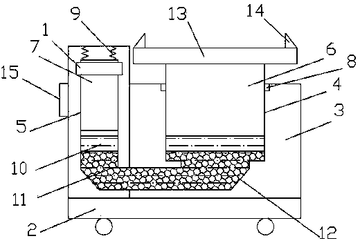
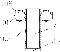
[0024] As shown in the figure, a hydraulic jack includes a driving device 1, a base 2 and a cylinder 3 that is movably connected to the base 2. The cylinder 3 is provided with a main lifting groove 4 and an auxiliary lifting groove 5 that communicate with each other at the bottom. The bottoms of the main lifting groove 4 and the auxiliary lifting groove 5 are respectively provided with chamfers 12 not less than 45°, and the main lifting blocks 6 that can be lifted and lowered along the inner wall of the groove are respectively arranged in the main lifting groove 4 and the auxiliary lifting groove 5 and the auxiliary lifting block 7, and are respectively connected by the sealing device I8 and the sealing device II16. Hydraulic oil 10 and pressure-bearing rolling balls 11 for enhancing the pressure-bearing performance of hydraulic oil 10. The...


PUM


Abstract

A hydraulic jack comprises a driving device, a base and a cylinder body which is movably connected with the base. The cylinder body is internally provided with a main hoisting groove and an auxiliary hoisting groove, the bottom of the main hoisting groove and the bottom of the auxiliary hoisting groove are communicated mutually, and the main hoisting groove and auxiliary hoisting groove are provided with a main hoisting block and an auxiliary hoisting block respectively, wherein the main hoisting block and the auxiliary hoisting block can ascend and descend along the inner wall of the main hoisting groove and the inner wall of the auxiliary hoisting groove respectively. The sealed space formed by the main hoisting block, the auxiliary hoisting block, the main hoisting groove and the auxiliary hoisting groove is injected with hydraulic oil and pressure-bearing grounders used for enhancing the pressure-bearing performance of the hydraulic oil. The driving device comprises two driving motors and racks, wherein the two driving motors are respectively provided with a driving gear, the racks are arranged on the auxiliary hoisting block and matched with the driving gears, and the rotation directions of the two driving motors are opposite to drive the driving gears to lift the auxiliary hoisting groove. Oil leaking and gas leaking are avoided when the hydraulic jack is used, the safety performance and the stability of the jack are improved, the occurrence that the using of the jack is affected when the hydraulic oil is polluted can be prevented, and the lifting speed and precision of the jack can be improved.

Description

technical field [0001] The invention relates to a lifting device, in particular to a hydraulic jack. Background technique [0002] The jack is one of the most widely used lifting equipment. The jack is divided into mechanical and hydraulic. Compared with the mechanical jack, the hydraulic jack has a larger lifting capacity, but its working principle is complicated and it is not suitable for carrying. Moreover, the hydraulic jack is working When it is necessary to reciprocate the handle, it is more labor-intensive and the lifting speed is slow. The oil is sucked from the oil tank through the oil suction check valve and pumped into the hydraulic cylinder through the oil discharge check valve to push the piston and the weight on the piston to move upward together. During the process, the hydraulic oil is prone to leakage when it passes through the oil suction check valve and the oil discharge check valve, which is not conducive to the safety and stability of the hydraulic jack....

Claims


Application Information

Patent Timeline
IPC IPC(8): B66F3/44
Inventor 焦燏烽赵果
Owner HENAN UNIV OF SCI & TECH
Learn More