
Compressed air engine hydraulically controlled high pressure intake system

A high-pressure air intake, compressed air technology, applied in the direction of engine components, machines/engines, mechanical equipment, etc., can solve problems such as high-pressure air switches that are difficult to solve, reduce pressure, reduce preload, and facilitate The effect of adjustment

Inactive Publication Date: 2016-03-02
DALIAN UNIV OF TECH +1
View PDF4 Cites 0 Cited by
  • Summary
  • Abstract
  • Description
  • Claims
  • Application Information

AI Technical Summary

Problems solved by technology

With the current materials, it is difficult to solve the switch problem of high-pressure high-pressure air

Method used


Image

  • Compressed air engine hydraulically controlled high pressure intake system
  • Compressed air engine hydraulically controlled high pressure intake system

Examples


Embodiment Construction

[0020] The present invention will be described in detail below in conjunction with the accompanying drawings.

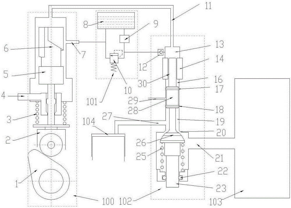
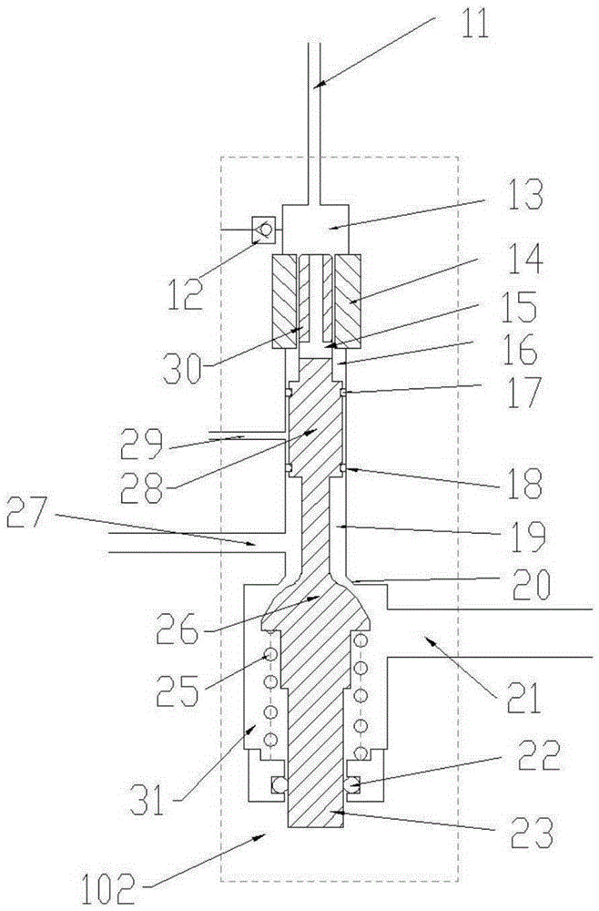
[0021] The compressed air engine hydraulically controls the high-pressure intake system, which is composed of a high-pressure oil pump 100, a high-pressure intake valve 102, a high-pressure gas tank 103 and a low-pressure oil delivery system 101; the low-pressure oil delivery system 101 provides the source of hydraulic oil required by the entire system; the high-pressure oil pump 100 provides the opening frequency and angle of the high-pressure intake valve 102 ; the high-pressure intake valve 102 inputs the high-pressure gas from the high-pressure gas tank 103 into the combustion chamber 104 .

[0022] The high-pressure oil pump 100 adopts a modified cam hydraulic plunger structure, cancels the oil inlet hole, retains the oil outlet hole 7, heightens the top surface of the hydraulic plunger 5, and the top of the hydraulic plunger 5 is always higher than the oil outle...


PUM


Abstract

The compressed air engine hydraulic control high-pressure intake system belongs to the field of compressed air engines and consists of a high-pressure oil pump (100), a high-pressure intake valve (102), a high-pressure air tank (103) and a low-pressure oil delivery system (101); The system (101) provides the source of hydraulic oil required by the entire system; the high-pressure oil pump (100) provides the opening frequency and angle of the high-pressure intake valve (102); the high-pressure intake valve (102) inputs the high-pressure gas from the high-pressure gas tank 103 into the combustion chamber (104). The invention adjusts the shift fork (4) of the high-pressure oil pump (100) to rotate the hydraulic plunger (5) at different angles, thereby changing the effective stroke of the hydraulic plunger and adjusting the opening angle of the valve.

Description

technical field [0001] The invention relates to a high-pressure air intake system for a compressed air engine. The system can control the high-pressure air in a high-pressure cylinder to directly work on the engine, instead of controlling the engine in a throttling manner after being stabilized. Background technique [0002] Reciprocating piston engine is the main form of compressed air engine used in automobiles. The traditional air intake method adopts cam, tappet, rocker arm, and intake valve air intake. There are also people who try to adopt electromagnetic valves to control the intake air. So far, there are no electromagnetic valves with high speed, high pressure, and large flow to come out. [0003] In the prior art, the cam intake valve intake method is used to control the intake of compressed air, which has the following defects [0004] The intake pressure is too high: the intake valve is subjected to high-pressure air, which causes the camshaft to be overstressed....

Claims


Application Information

Patent Timeline
Patent Type & Authority Patents(China)
IPC IPC(8): F01L9/02F01L9/12
Inventor 孙培岩满长忠唐运榜孙新雨黄平赵百东高新宋海波辛志鹏
Owner DALIAN UNIV OF TECH
Learn More