Water inlet and outlet pipe of water heater

A technology for water inlet and outlet pipes and water heater tanks, which is applied to fluid heaters, lighting and heating equipment, etc., and can solve problems such as high manufacturing costs, complicated installation, and complicated manufacturing processes

Active Publication Date: 2014-05-28
嘉兴劲境电子商务有限公司
4 Cites 1 Cited by

AI-Extracted Technical Summary

Problems solved by technology

[0002] At present, the common inlet and outlet pipes are generally composed of stainless steel outer pipe and plastic inner pipe. The stainless steel outer pipe and plastic inner pipe are connected by multiple injection moldings. The manufacturing process is relatively complicated and the manufacturing cost is high.
The existing waterproof wall technology cannot completely solve the leakage problem of the water heater, especially the environmental leakage
For the safety of the shower, a leakage protector is ge...

Method used

If the base body 11 bottom of the pipe base is connected to the water inlet outer pipe, water enters the inner pipe 4 by the water inlet outer pipe through the water pipe seat, flows out from the inner pipe water outlet 3 at the top of the inner pipe, and enters the outer pipe 6 and the inner pipe 4 Between, flow in the water heater water tank by outer pipe water outlet 7 again. The water infiltrated into the cavi...

Abstract

A water inlet and outlet pipe of a water heater comprises a water pipe body and a water pipe seat, wherein the water pipe body is arranged in a water tank of the water heater, the water pipe seat is arranged outside the water tank of the water heater, and the water pipe body and the water pipe seat are connected integrally. A sealing plug is connected at the top end of an inner pipe in a buckled manner, the top end of the sealing plug is clamped in a plug support seat which is connected at the top end of an outer pipe in a clamped manner, a through hole fitted with the inner pipe is formed in an axis of an outer pipe support, the inner pipe is serially connected in the through hole, and the bottom end of the outer pipe is connected on the outer pipe support in a clamped manner to form the water pipe body. The water inlet and outlet pipe of the water heater has the advantages that structures of component parts are simple, multiple times of injection molding is replaced by buckling connection, and machining difficulty is lowered. The water pipe seat comprises a pipe seat base body and a detecting male tab, a hollow cavity is formed in an axis of the pipe seat base body, and the detecting male tab is fixed on the pipe seat base body via a screw. The detecting male tab is capable of detecting whether water in the water tank is electrified, so that dangers from electric leakage of the water heater and environmental electric leakage are avoided.

Application Domain

Fluid heaters

Technology Topic

Pipe supportWater pipe +3

Image

  • Water inlet and outlet pipe of water heater
  • Water inlet and outlet pipe of water heater
  • Water inlet and outlet pipe of water heater

Examples

  • Experimental program(1)

Example Embodiment

[0025] Attached Figure 1 to 4 The specific implementation of the invention is further explained:
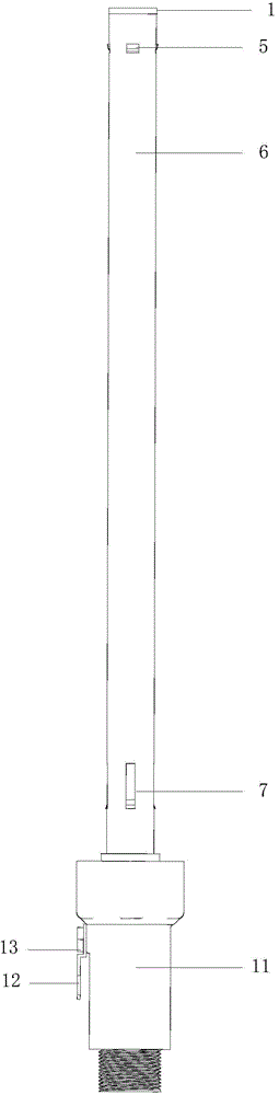
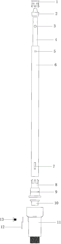
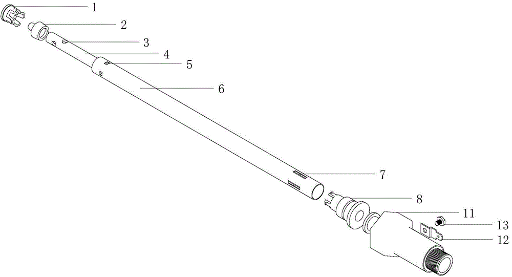
[0026] A water heater inlet and outlet pipe includes a water pipe body and a water pipe seat. The water pipe body is located in the water heater water tank, the water pipe seat is located outside the water heater water tank, and the water pipe body and the water pipe seat are connected as a whole. The water pipe body includes an inner pipe 4, an outer pipe 6, a sealing plug 2, a plug support 1 and an outer pipe bracket 8. The plug support 1 is provided with a claw. The outer tube 6 is a stainless steel tube, the length of the outer tube is adapted to the inner tube, the top of the outer tube is provided with an assembly hole 5, the claw of the plug support 1 is clamped in the assembly hole 5, and the bottom end of the outer tube is provided with an outer Pipe water port 7. The inner tube 4 is a plastic tube, and the inner tube is slender and has an inner tube water port 3 at the top. The shaft of the outer tube bracket 8 is provided with a through hole that fits the inner tube 4; the outer tube bracket 8 is provided with claws, the end of the outer tube bracket 8 is provided with a boss, and the middle part is provided with a sealing ring positioning groove 9 and a positioning groove 9 A sealing ring is installed inside. The inner tube 4 is sleeved in the outer tube 6, the bottom end of the sealing plug 2 is buckled to the top of the inner tube 4, the top end of the sealing plug 2 is clamped in the plug support 1, and the claw of the plug support 1 is clamped on the outer tube 6. In the assembly hole 5 at the top end, the inner tube 4 is serially connected in the through hole of the outer tube bracket 8, and the claws of the outer tube bracket 8 are clamped into the water port at the bottom end of the outer tube 6 to form a water tube body. The structure of each component is simple, and the snap connection replaces multiple injection molding, which reduces the processing difficulty.
[0027] The water pipe holder includes a pipe holder base 11 and a detecting insert 12. The pipe holder base 11 has a hollow cavity 14 at its axis. The detecting insert 12 is fixed on the pipe holder base 11 by a screw 13, and the screw 11 contacts the water in the hollow cavity 14. The detection insert 12 is connected with a leakage detection device. Sealing rings are placed between the screw 13 and the detection insert 12 and between the detection insert 12 and the base 11 of the socket. One end of the base 11 of the pipe socket is provided with an internal thread as the first connection end, and a clamping platform 15 is provided inside the first connection end; one end of the base 11 of the pipe socket is equipped with an external thread as the second connection end, and a sealing platform is provided inside the second connection end 16. There is a high elastic sealing ring 10 in the sealing platform.
[0028] The convex edge of the outer tube bracket 8 is clamped on the clamping platform of the first connecting end of the pipe socket base 11, and the internal thread of the first connecting end is screwed with a fixing nut. There is no sealing ring between the convex edge and the clamping platform 15, so that The water in the inner tank seeps into the hollow cavity. A sealing ring is installed in the sealing ring positioning groove 9 of the outer pipe bracket 8 to make the inlet and outlet water pipes and the water tank hermetically connected. The bottom end of the inner tube 4 is clamped in the high elastic sealing ring 10 in the sealing platform 16 to prevent water leakage. The water pipe body and the water pipe holder are connected as a whole. The second connection end of the pipe holder base is connected to the external water pipe, and the second connection end is connected to the outside A sealing ring is installed between the water pipes to seal the inner pipe and the outer water pipe.
[0029] If the bottom end of the base 11 of the pipe seat is connected to the outer water inlet pipe, water enters the inner pipe 4 from the outer water inlet pipe through the water pipe seat, flows out from the inner pipe water port 3 at the top of the inner pipe, and enters between the outer pipe 6 and the inner pipe 4. Then, it flows into the water tank of the water heater through the water port 7 of the outer pipe. The water penetrating into the hollow cavity 14 of the pipe seat is the water between the outer pipe and the inner pipe, and the outer pipe is made of stainless steel and is connected with the water in the water tank. The detection insert is connected with a leakage detection device, which can effectively detect whether the water in the water tank is charged, so as to avoid the harm caused by the leakage of the water heater itself and the environment.
[0030] Of course, the above descriptions are only preferred embodiments of the present invention, and the present invention is not limited to the above-mentioned embodiments. It should be noted that all equivalent substitutions made by any person skilled in the art under the guidance of this specification The obvious deformation forms fall within the essential scope of this specification and should be protected by the present invention.

PUM

no PUM

Description & Claims & Application Information

We can also present the details of the Description, Claims and Application information to help users get a comprehensive understanding of the technical details of the patent, such as background art, summary of invention, brief description of drawings, description of embodiments, and other original content. On the other hand, users can also determine the specific scope of protection of the technology through the list of claims; as well as understand the changes in the life cycle of the technology with the presentation of the patent timeline. Login to view more.
Why Eureka
Try Eureka