Supercharge Your Innovation With Domain-Expert AI Agents!

An n×m Optical Switch

An optical switch and optical path technology, applied in the field of N×M optical switches, can solve problems such as poor long-term stability, large insertion loss, and complex system structure, and achieve high reliability, low optical insertion loss, and strong operability

Active Publication Date: 2016-05-11
SHANGHAI BRANCH FUZHOU GAOYI COMM CO LTD
View PDF7 Cites 0 Cited by
  • Summary
  • Abstract
  • Description
  • Claims
  • Application Information

AI Technical Summary

Problems solved by technology

Now the market demands optical switches with 100×100 channels or even larger capacity. If the above method is still used, although the implementation method is relatively simple, there are many shortcomings: large insertion loss, poor long-term stability, and the system structure is too complicated

Method used


Image

  • An n×m Optical Switch
  • An n×m Optical Switch
  • An n×m Optical Switch

Examples


Embodiment Construction

[0015] The present invention will be further described below in conjunction with the accompanying drawings and specific embodiments.

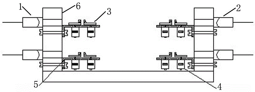
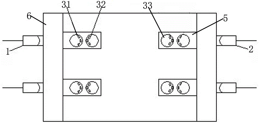
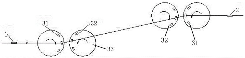
[0016] The N×M optical switch of the present invention adopts two drivers behind each input collimator 1 at the input end to respectively drive two disks 33 to rotate, and two groups of optical path deflection elements are arranged on the two disks 33 to respectively make the input The light is deflected at a certain angle in the horizontal and vertical directions, so that the light beam is incident on the optical path deflection unit corresponding to the output end, and the optical path deflection unit in front of the output collimator 2 at the output end also adopts two sets of corresponding optical path deflection elements, The incident light beam deflected from the input end is deflected again in the horizontal and vertical directions and finally coupled into the output collimator to realize the switching of the optical path. Specifically, ...


PUM


Abstract

The invention relates to the field of optical communication, and discloses an N*M optical switch. The N*M optical switch comprises an input and output unit, an optical path deflection unit and (2N+2M) drivers. The input and output unit comprises N input collimators and M output collimators; the optical path deflection unit comprises (N+M) groups of horizontal optical path deflection elements and (N+M) groups of vertical optical path deflection elements, and each group of horizontal or vertical optical path deflection elements are respectively connected with a driver; and a group of horizontal optical path deflection elements and a group of vertical optical path deflection elements are correspondingly arranged behind each input collimator, and a group of horizontal optical path deflection elements and a group of vertical optical path deflection elements are correspondingly arranged in front of each output collimator. Such a structure utilizes different refraction angles of light by different-angle wedge angle prisms to realize a large-capacity optical switch and employs a stepping motor to drive the switching of the different-angle wedge angle prisms so that the reliability is high and the operability is high; and there are fewer optical elements on an optical path so that the optical insertion of such a structure is small in loss.

Description

technical field [0001] The invention relates to the field of optical communication, in particular to an N*M optical switch. Background technique [0002] An optical switch is an optical component that can change the transmission path of light beams and has high stability and precision. Its function is to perform mutual conversion or logical operation on optical signals in optical transmission lines or integrated optical circuits. Optical signals can be switched on and off in the optical network system. Optical switches are widely used in Optical Add / Drop Multiplexing (OADM), Time Division Multiplexing (TDM), and Wavelength Division Multiplexing (WDM), and are key devices for realizing All Optical Networks (AON). It has a broad market prospect and is one of the most promising optical passive devices. [0003] Judging from the current situation, most N×M mechanical optical switch arrays are assembled through 1×2 and 2×2 switching. Now the market demands optical switches wit...

Claims


Application Information

Patent Timeline
Patent Type & Authority Patents(China)
IPC IPC(8): G02B26/08
Inventor 吴砺凌吉武赵振宇林江铭杨建阳任策
Owner SHANGHAI BRANCH FUZHOU GAOYI COMM CO LTD
Features
  • R&D
  • Intellectual Property
  • Life Sciences
  • Materials
  • Tech Scout
  • Unparalleled Data Quality
  • Higher Quality Content
  • 60% Fewer Hallucinations
Learn More