Cylinder type centrifugal extractor

A centrifugal extractor and cylindrical technology, which is applied in the direction of liquid solution solvent extraction, etc., can solve the problem of obvious vibration of the centrifugal extractor, affecting the processing flux and efficiency of the centrifugal extractor, and the short residence time of the heavy phase, which cannot be separated well, etc. problems, to achieve good extraction and separation effects, small phase entrainment, and improved productivity

Active Publication Date: 2014-06-04
广州富一液体分离技术有限公司
View PDF9 Cites 21 Cited by
  • Summary
  • Abstract
  • Description
  • Claims
  • Application Information

AI Technical Summary

Problems solved by technology

The disadvantage of this traditional centrifugal extractor is that since the heavy phase diversion holes and flow control holes are arranged axially, after the motor is started, the two-phase materials are mixed and separated, and rise from the drum very quickly, and the heavy phase quickly The heavy phase directly flows out from the diversion hole and the flow control hole, resulting in the short residence time of the heavy phase in the drum, which cannot be separated well, especially when the speed increases, the heavy phase is obviously entrained, which cannot
[0004] The stability of the page is well controlled, and if the pore size of the flow control hole is limited, although the phenome...

Method used


Image

  • Cylinder type centrifugal extractor

Examples


Embodiment

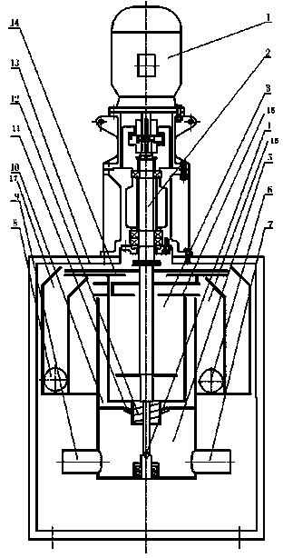
[0023] like figure 1 As shown, the cylindrical centrifugal extractor includes motor 1, transmission system 2, drum 3, auxiliary support 4, mixing chamber 5, light phase outlet 6, light phase inlet 7, heavy phase outlet 8, heavy phase Phase inlet 9, interlayer 10, annular impeller 11, feed impeller 12, frame 13, light phase weir plate 15, heavy phase weir plate 14, light phase collection chamber 16 and heavy phase collection chamber 17;

[0024] One end of the transmission system 2 is connected to the motor 1, and the other end of the transmission system 2 is connected to the top of the rotating shaft of the drum 3. The bottom of the rotating shaft of the rotating drum 3 is provided with an auxiliary support 4, and the lower part of the rotating drum 3 is provided with a stopper. A flow plate, a feed impeller 12 is provided below the center position of the bottom of the drum 3, a mixing chamber 5 is provided below the drum 3, mixing baffles are provided on the periphery and bot...


PUM


Abstract

The invention discloses a cylinder type centrifugal extractor. The centrifugal extractor comprises a motor, a transmission system, a rotating shaft, an auxiliary support, a mixing chamber, a light-phase outlet, a light-phase inlet, a heavy-phase outlet, a heavy-phase inlet, a sandwich layer, an annular impeller, a feeding impeller, a rack, a light-phase weir plate, a heavy-phase weir plate, a light-phase collecting chamber and a heavy-phase collecting chamber, wherein one end of the transmission system is connected with the motor, and the other end of the transmission system is connected with the top of the rotating shaft of a rotor drum; the bottom of the rotating shaft of the rotor drum is provided with the auxiliary support; the bottom of the rotor drum is provided with a baffle plate; the feeding impeller is arranged under the central position of the bottom of the rotor drum; the mixing chamber is arranged below the rotor drum; both the periphery and the bottom of the mixing chamber are provided with mixing baffle plates; the heavy-phase inlet and the light-phase inlet are respectively formed in the two ends of the bottom of the mixing chamber; the exterior of the rotor drum is provided with the sandwich layer, the light-phase collecting chamber and the heavy-phase collecting chamber from the inside out. The cylinder type centrifugal extractor has the advantages that entrainment is reduced, the extraction flux is increased, an extraction separation effect is good, the production efficiency is high, and the like.

Description

technical field [0001] The invention relates to the field of chemical machinery products, in particular to a cylindrical centrifugal extractor. Background technique [0002] Centrifugal extractor is a high-efficiency liquid-liquid extraction equipment designed using the principle of extraction and separation. It is widely used in hydrometallurgy, medicine, fine chemical industry and other fields. The main structure of a traditional centrifugal extractor includes a motor, a diversion body, a drum and a casing. A partition is arranged in the diversion body, and a light-phase diversion hole is arranged under the partition. An axial heavy phase diversion hole is formed, a heavy phase weir is arranged above the diversion body, an axial flow control hole is arranged on the heavy phase weir, and a material inlet, a heavy phase outlet and a light phase outlet are arranged on the shell. For details, refer to the XS-34 (ring) centrifugal extractor in "Cylindrical Centrifugal Extracto...

Claims


Application Information

Patent Timeline
IPC IPC(8): B01D11/04
Inventor 苏剑平张进韬黄冬梅
Owner 广州富一液体分离技术有限公司
Why Eureka
Try Eureka