Denitrification operation optimization method of SCR (selective catalytic reduction) system of W flame boiler

An SCR system and operation optimization technology, applied in chemical instruments and methods, separation methods, dispersed particle separation, etc., can solve the problems of reduced denitration efficiency, no consideration, fly ash pollution, etc.

Inactive Publication Date: 2014-06-04
HUAZHONG UNIV OF SCI & TECH
View PDF6 Cites 16 Cited by
  • Summary
  • Abstract
  • Description
  • Claims
  • Application Information

AI Technical Summary

Problems solved by technology

When its molar ratio is small, NO x with NH 3 Incomplete response, NO x low conversion rate
When the molar ratio exceeds a certain range, NO x The conversion rate no longer increases, causing the reducing agent NH 3 The waste of ammonia slip increases
[0011] (4) Ammonia escape rate
[0012] If NH 3 If the quantity is not well controlled, it will not only increase the cost, but also cause two main problems: corrosion of the heat exchange surface of the air preheater and pollution of fly ash
[0017] However, in actual operation, the following problems exist in the operation of the SCR system: (1) The denitrification efficiency is lower than the design value, and the NO x The emission cannot meet the environmental protection standard; (2) Incomplete reaction leads to some NH 3 escape, and the operating cost increases; (3) NH 3 Escaping causes secondary pollution, leading to corrosion and blockage of air preheaters and o

Method used


Image

  • Denitrification operation optimization method of SCR (selective catalytic reduction) system of W flame boiler
  • Denitrification operation optimization method of SCR (selective catalytic reduction) system of W flame boiler
  • Denitrification operation optimization method of SCR (selective catalytic reduction) system of W flame boiler

Examples


Embodiment Construction

[0037] In order to make the object, technical solution and advantages of the present invention clearer, the present invention will be further described in detail below in conjunction with the accompanying drawings and embodiments. It should be understood that the specific embodiments described here are only used to explain the present invention, not to limit the present invention. In addition, the technical features involved in the various embodiments of the present invention described below can be combined with each other as long as they do not constitute a conflict with each other.

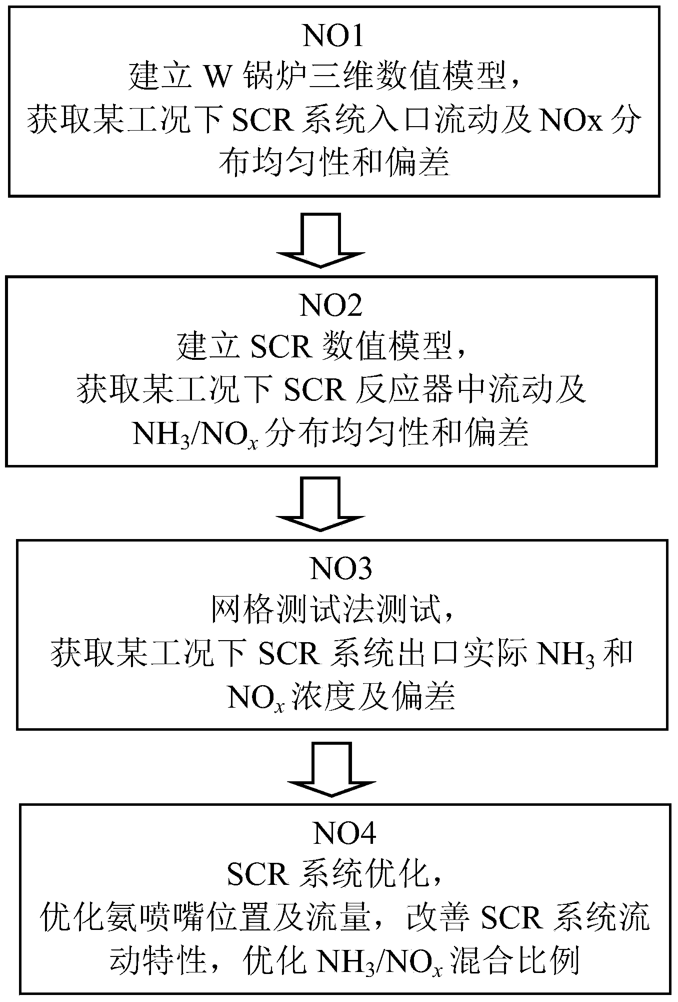
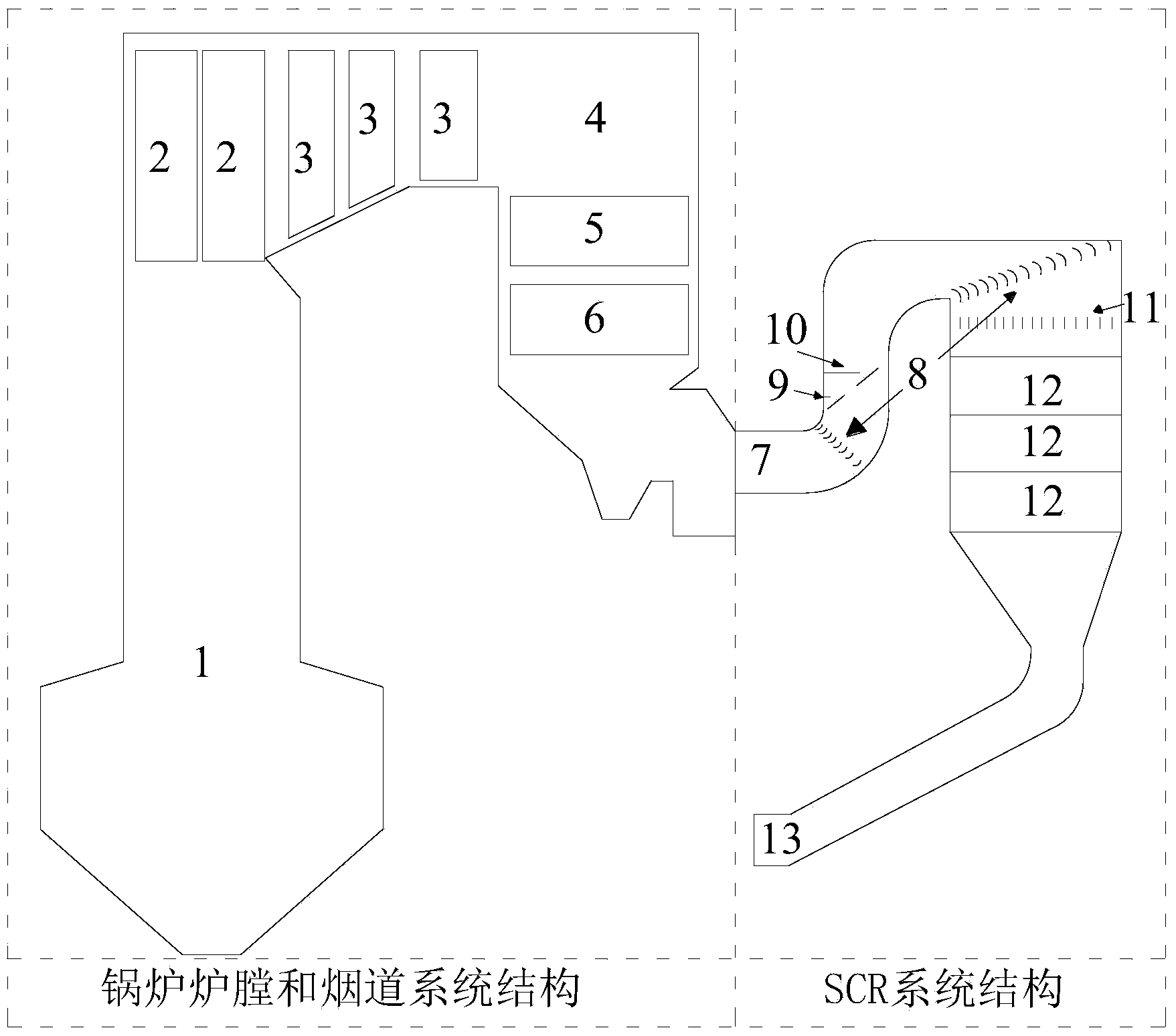
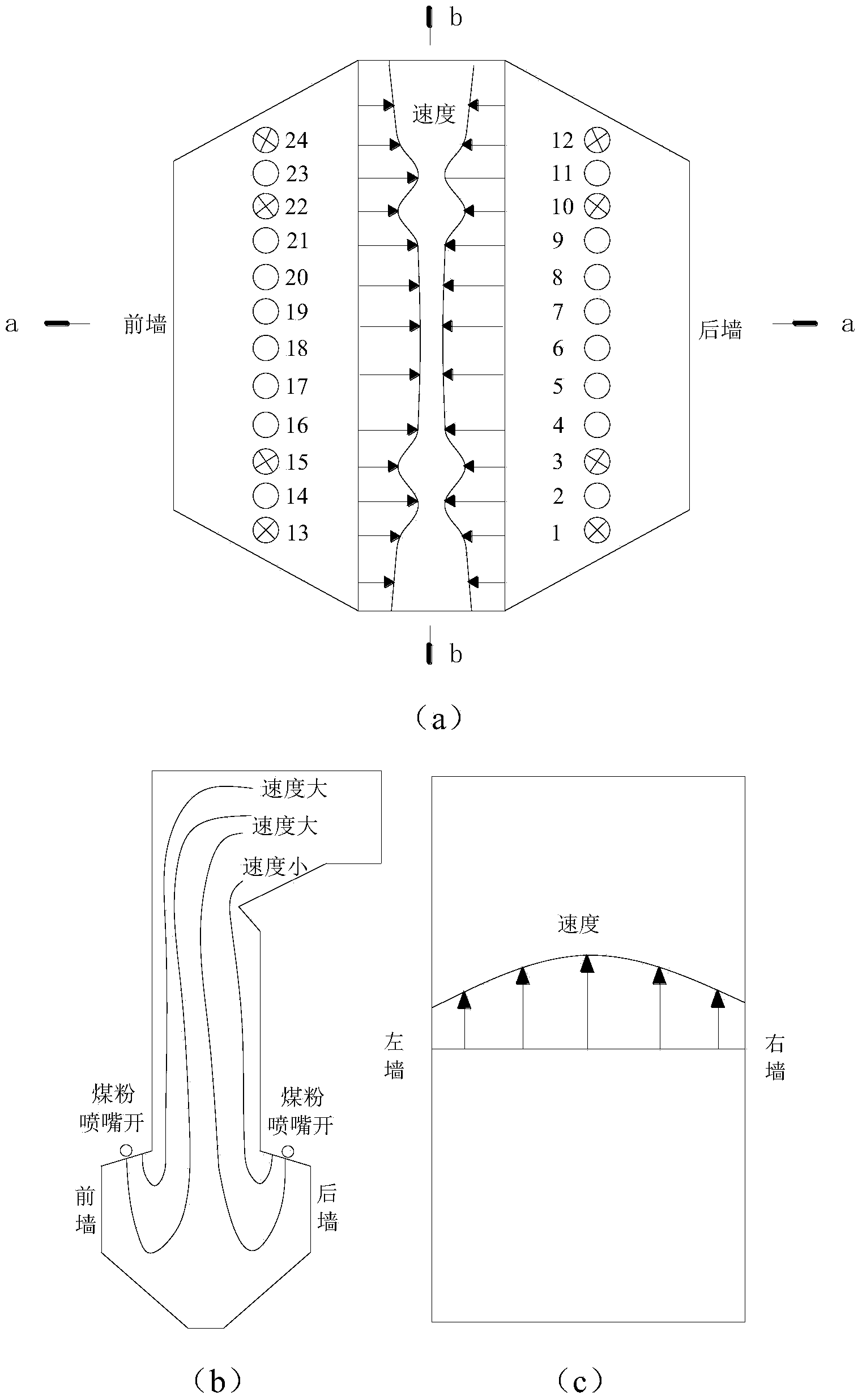
[0038] The invention provides an SCR system denitrification operation optimization method for improving the denitrification efficiency of the SCR system of a W-shaped flame boiler, reducing its operation cost and improving the operation safety of the boiler system. This method considers the influence of boiler operating conditions, boiler furnace and flue structure, and SCR system structure at t...


PUM


Abstract

The invention discloses a denitrification operation optimization method of a SCR (selective catalytic reduction) system of a W flame boiler. The denitrification operation optimization method particularly comprises the following steps: acquiring the smoke flow speed and the NOx concentration distribution uniformity and deviation at an outlet of a boiler by considering the structure and the running working condition of a W flame boiler so as to act as inlet boundary conditions of a rear-stage SCR system; adjusting the ammonia spraying flow rate corresponding to the region at which the flue flow speed is slightly high and the NH3/NOx is slightly low to be low, increasing the number of ammonia spraying nozzles, and adjusting the ammonia spraying flow rate corresponding to a region at which the flue flow speed is slightly slow and the NH3/NOx is slightly high to be low when the standard criterion that the ammonia spraying flow rate at the upper layer is higher than that at the lower layer, and the ammonia spraying flow rate at the middle is higher than that at two sides is met. According to the invention, the structures and the running situation of the boiler and the SCR system are optimized and adjusted, the denitrification efficiency of the SCR system is improved; the spraying-in quantity and the escape rate of ammonia are reduced.

Description

technical field [0001] The invention belongs to the technical field of pulverized coal combustion denitrification, and in particular relates to a denitrification operation optimization method for an SCR system of a coal-fired boiler, and is especially suitable for W-type flame coal-fired boilers. Background technique [0002] China's primary energy consumption is dominated by coal, accounting for more than 70% of primary energy consumption, and this coal-based energy structure will not change in the future. Nitrogen oxides (NO, NO 2 and N 2 O, collectively referred to as NO x ) emission is one of the main sources of air pollutants. NO x It will directly endanger human health, and also lead to the formation of acid rain and photochemical smog and cause the atmospheric greenhouse effect. W flame boiler is especially suitable for the combustion of low-volatile low-quality coal, but the NOx emission is relatively large. The new "Emission Standard of Air Pollutants for Therm...

Claims


Application Information

Patent Timeline
IPC IPC(8): B01D53/90B01D53/56
Inventor 方庆艳马仑乐方愿张成陈刚
Owner HUAZHONG UNIV OF SCI & TECH
Why Eureka
Try Eureka