
Laser drilling method and laser drilling system

A laser drilling and laser beam technology, which is used in laser welding equipment, glass manufacturing equipment, welding/welding/cutting items, etc., can solve the problem of poor surface quality of hole processing and the inability of laser drilling method to adapt to ultra-high chemical strength substrate materials and other problems to achieve the effect of ensuring quality

Active Publication Date: 2016-01-20
HEFEI XINSHENG OPTOELECTRONICS TECH CO LTD +1
View PDF8 Cites 0 Cited by
  • Summary
  • Abstract
  • Description
  • Claims
  • Application Information

AI Technical Summary

Problems solved by technology

[0004] The purpose of the technical solution of the present invention is to provide a laser drilling method and a laser drilling system, which are used to solve the problem that the laser drilling method in the prior art cannot be adapted to substrate materials with ultra-high chemical strength, and the surface quality of hole processing is poor

Method used


Image

  • Laser drilling method and laser drilling system
  • Laser drilling method and laser drilling system
  • Laser drilling method and laser drilling system

Examples


Embodiment Construction

[0040] In order to make the technical problems, technical solutions and advantages to be solved by the present invention clearer, the following will describe in detail with reference to specific embodiments and accompanying drawings.

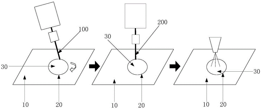
[0041] figure 2 It is a schematic structural diagram of the principle structure of the laser drilling method described in a specific embodiment of the present invention, combined with figure 2 , the laser drilling method described in a specific embodiment of the present invention, comprising:

[0042] Step 1, hole boundary forming step: output pulsed laser beam 100, scan on the substrate 10 to be punched, and form the boundary cutting groove 20 of the preformed hole;

[0043] Step 2, material heating step in the hole: output CO 2 laser beam 200, making the CO 2 The laser beam 200 is aligned with the pre-formed hole, and the substrate material 30 of the pre-formed hole is heated for a predetermined time;

[0044] Step 3, hole forming step: ...


PUM


Abstract

The present disclosure provides a laser drilling method and a laser drilling system. The laser drilling method includes a hole-boundary formation step of outputting a pulse laser beam and scanning a substrate to be drilled, to form a boundary cutting groove of a preformed hole; a material-in-hole heating step of outputting a CO2 laser beam, aligning the CO2 laser beam with the preformed hole, and heating a substrate material of the preformed hole for a predetermined period of time; and a hole formation step of cooling the substrate material of the preformed hole, to deform the substrate material and enable the substrate material to fall off from the substrate to be drilled.

Description

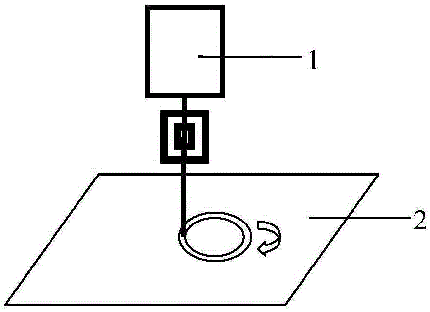
technical field [0001] The invention relates to the technical field of laser processing, in particular to a laser drilling method and a laser drilling system. Background technique [0002] Laser drilling refers to the laser processing process in which the laser is focused and used as a high-intensity heat source to heat the material, so that the material in the laser action area is melted or vaporized and then evaporated, thereby forming a hole. At present, the existing laser drilling technology mainly uses CO 2 Continuous laser, the working principle diagram is as follows figure 1 As shown, CO 2 The laser 1 outputs continuous laser light, and performs high-temperature focusing on the substrate 2 along the edge area to be drilled to melt the material and realize the drilling. [0003] However, due to the use of CO 2 When laser drilling, for some substrates, such as ultra-high chemical strength glass substrates, the whole piece is prone to fragmentation, so for glass subs...

Claims


Application Information

Patent Timeline
Patent Type & Authority Patents(China)
IPC IPC(8): B23K26/382B23K26/0622B23K26/03B23K26/16B23K26/14B23K26/70
CPCC03B33/091B23K26/032B23K26/0622B23K26/142B23K26/388B23K26/389B23K26/40B23K26/402B23K26/703B23K2103/00B23K2103/42B23K2103/54C03B33/0222C03B33/04
Inventor 董岱公伟刚黄阳陶胜
Owner HEFEI XINSHENG OPTOELECTRONICS TECH CO LTD
Learn More