An evaporation source baffle structure

A technology of baffle structure and evaporation source, which is applied in the direction of vacuum evaporation plating, ion implantation plating, metal material coating technology, etc., can solve the problems of internal stress imbalance, material blocking effect is not obvious, material falling off, etc., to achieve The effect of increasing the adhesion rate and reducing the risk of cross-contamination

Active Publication Date: 2016-05-18
EVERDISPLAY OPTRONICS (SHANGHAI) CO LTD
View PDF6 Cites 0 Cited by
  • Summary
  • Abstract
  • Description
  • Claims
  • Application Information

AI Technical Summary

Problems solved by technology

[0004] 1. The blocking effect on materials is not obvious, and it is easy to cause cross-contamination of materials
If the area of ​​the metal baffle is too small, or when the evaporation rate of the material is relatively large, the adsorption efficiency of the metal baffle to the material is not good, which will cause material cross-contamination;
[0005] 2. The adsorbed material is easy to fall off, causing the crucible to block the hole
Since the uniformity of materials deposited on the baffle is different, this will lead to unbalanced internal stress and weight of the material deposited on the baffle, which will easily cause the material to fall off;
[0006] 3. Ordinary cover-type baffles are easy to form material accumulation at the edge and cause material overflow
Due to the small chamber of the test line, the area of ​​the generally designed cover baffle is relatively small, and it cannot ensure that the evaporation source is in the middle of the baffle, which will cause the material to accumulate at the edge, resulting in material falling off or material overflow or even There is a hole blocking phenomenon

Method used


Image

  • An evaporation source baffle structure

Examples


Embodiment Construction

[0028] The following will clearly and completely describe the technical solutions in the embodiments of the present invention with reference to the accompanying drawings in the embodiments of the present invention. Obviously, the described embodiments are only some, not all, embodiments of the present invention. Based on the embodiments of the present invention, all other embodiments obtained by persons of ordinary skill in the art without creative efforts fall within the protection scope of the present invention.

[0029] It should be noted that, in the case of no conflict, the embodiments of the present invention and the features in the embodiments can be combined with each other.

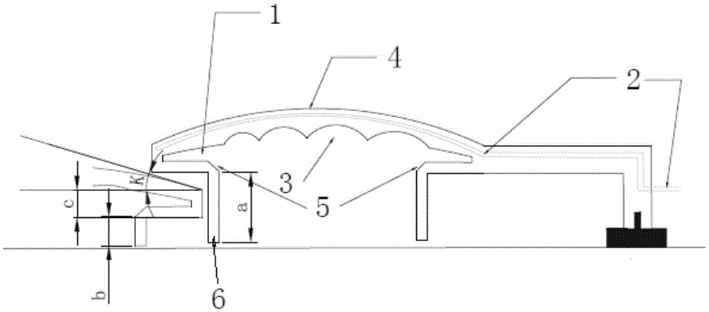
[0030] An evaporation source baffle structure of the present invention includes several metal baffles that are adjacent to each other but not in contact, refer to figure 1 , the metal baffle includes an arc-shaped shading surface 4, the side of the shading surface 4 facing away from the evaporati...


PUM


Abstract

The invention discloses an evaporation source check plate structure. The evaporation source check plate structure comprises a plurality of adjoining but contactless metal check plates, wherein each metal check plate comprises an arc shielding surface, the side of the arc shielding surface, back on to the evaporation source, is convex, the side of the arc shielding surface, facing toward the evaporation source, is concave, the cambered surface angles of the shielding surfaces of two adjacent metal check plates are the same, two ends of the shielding surface are respectively bent toward the direction of the evaporation source so as to form two lower edges of the same length, and an inward concave opening is formed between the lower edge and the shielding surface. By adopting the evaporation source check plate structure, the problem in the OLED (organic light emitting diode) test line and volume production line that a few materials are simultaneously heated in a cavity so as to cause material cross contamination is effectively solved; in the OLED test line and volume production line, holes are effectively prevented from being blocked by falling materials excessively deposited on the evaporation source check plate; used OLED material can be well collected so as to be recycled and purified, thus lowering the cost.

Description

technical field [0001] The invention relates to the technical field of vacuum coating, in particular to an evaporation source baffle structure. Background technique [0002] The vacuum thermal evaporation coating process includes a variety of process control methods such as deposition rate, vacuum degree, and substrate temperature. The deposition rate control mainly determines the aggregation density and thickness uniformity of the optical thin film, and has a direct impact on the control of the film thickness. Different The deposition rate can make a significant difference in the spectral and mechanical properties of the film. The vacuum evaporation coating machine mainly controls the evaporation rate of the material by adjusting the evaporation current or the electron beam current, and controls the start and end of the coating process through the rotation of the baffle. [0003] Most of the current evaporation source baffles are directly made of metal baffles and then put...

Claims


Application Information

Patent Timeline
Patent Type & Authority Patents(China)
IPC IPC(8): C23C14/24
Inventor 王钊林信志张斌倪蔚德
Owner EVERDISPLAY OPTRONICS (SHANGHAI) CO LTD
Why Eureka
Try Eureka