Transmission structure for wind driven generator
A wind turbine and transmission structure technology, applied to wind turbine components, wind engines, wind power generation, etc., can solve the problems of frequent maintenance and even replacement of the transmission structure, failure to reach the designed service life, complex disassembly and assembly of the transmission structure, etc., to achieve Ease of disassembly and maintenance, reduction of bending stress, and improvement of power transmission capability
- Summary
- Abstract
- Description
- Claims
- Application Information
AI Technical Summary
Problems solved by technology
Method used
Image

Examples
Embodiment 1
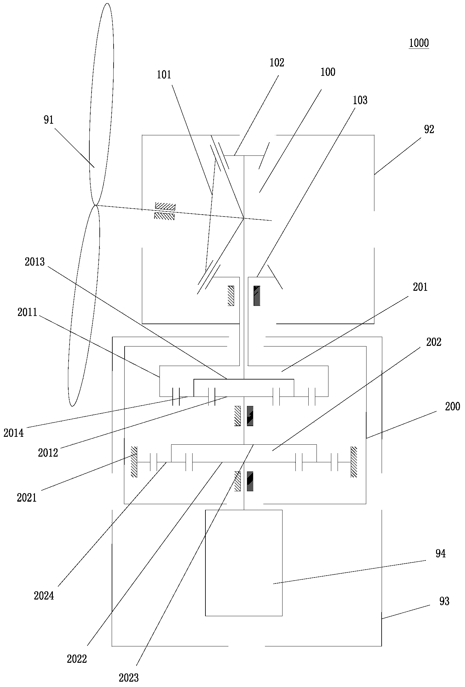
[0029] Such as figure 1 As shown, the present invention proposes a wind power generator transmission structure 1000, the wind power generator includes a tower 93 and a cabin 92 arranged on the top of the tower 93; The spiral bevel gear mechanism 100 is composed of a planetary gear speed-up box 200 arranged in the tower 93; the impeller 91 of the wind power generator is connected to the input shaft of the spiral bevel gear mechanism 100, and the output shaft of the spiral bevel gear mechanism 100 is connected to the planetary gear The input shaft of speed-up box 200, the output shaft of planetary gear speed-up box 200 is connected to the rotating shaft of generator set 94; The output shaft of described spiral bevel gear mechanism 100, the input shaft and output shaft of planetary gear speed-up box 200 are coaxial set, and in the same direction as the axis of the tower 93.
[0030] From the above, the transmission structure of the wind power generator of the present invention a...
Embodiment 2
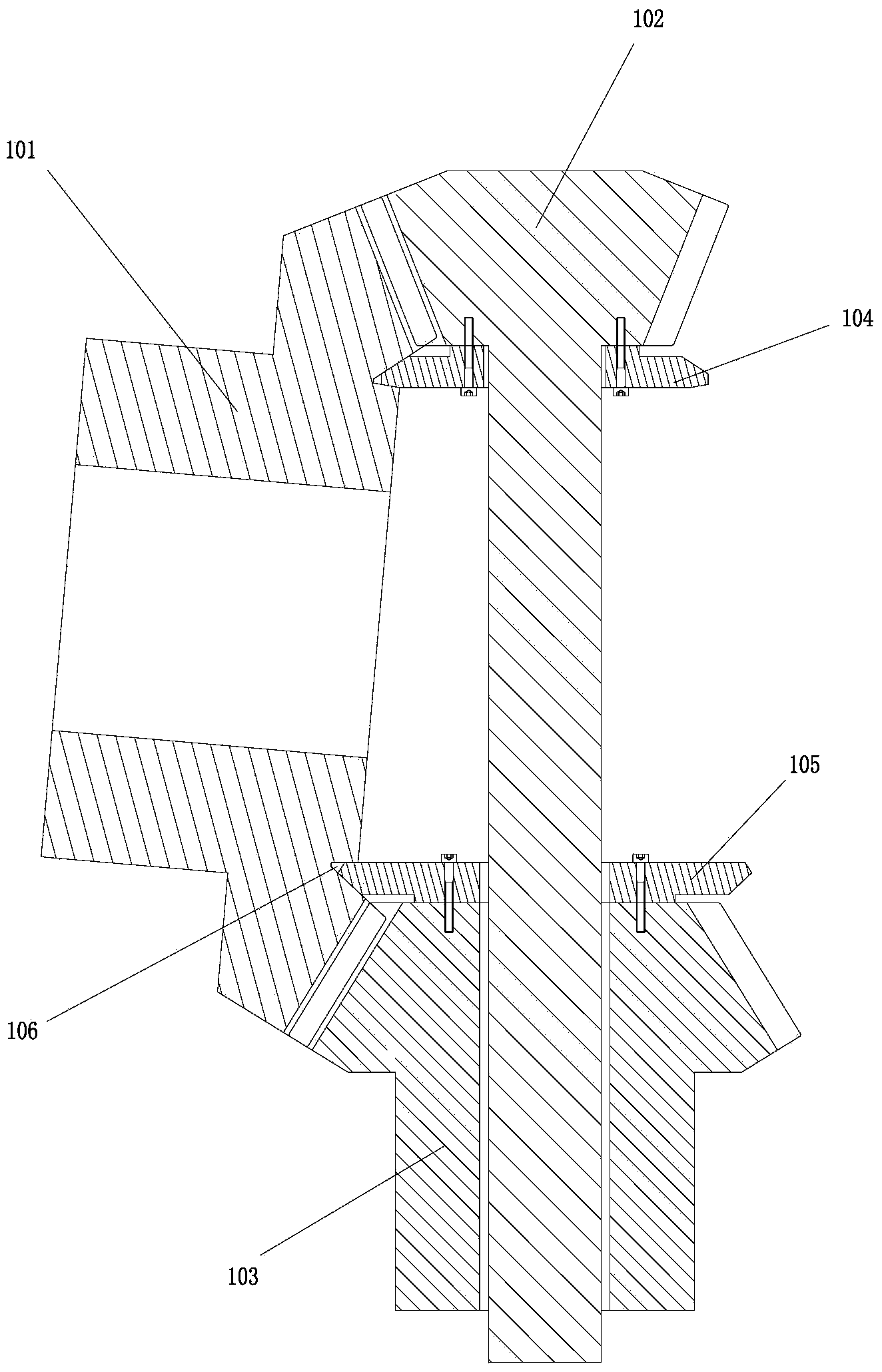
[0049] The structure and principle of this embodiment are basically the same as that of Embodiment 1, the difference is that figure 2 As shown, the first driven spiral bevel gear 102 is fixed with a first thrust plate 104, and the second driven spiral bevel gear 103 is fixed with a second thrust plate 105; The end surface of the gear 101 is provided with a corresponding annular groove 106 , and the edges of the first thrust plate 104 and the second thrust plate 105 are rotatably locked in the annular groove 106 .
[0050] The first thrust plate 104 cooperates with the annular groove 106 to offset the axial force on the first driven spiral bevel gear 102; the second thrust plate 105 cooperates with the annular groove 106 to offset the Axial force on the second driven helical bevel gear 103 ; thus, setting a thrust bearing on the corresponding rotating shaft can be omitted to reduce costs. Even if a thrust bearing is provided on a corresponding rotating shaft, it can prevent t...
Embodiment 3
[0056] The structure and principle of this embodiment are basically the same as that of Embodiment 1, the difference is that in Embodiment 1, the planetary gear speed-up box is composed of a two-stage planetary gear mechanism; and in this embodiment, the planetary The gear speed-up box is composed of a first-stage planetary gear mechanism and a first-stage fixed-axis gear train (not shown in the figure).
[0057] The planetary gear mechanism includes a ring gear, a sun gear and a planet carrier, and the planet carrier is provided with a plurality of planetary gears meshing with the ring gear and the sun gear; the planet carrier is connected to the rotating shaft of the first driven spiral bevel gear, The ring gear is connected to the rotating shaft of the second driven spiral bevel gear, and the planetary carrier and the ring gear together constitute the input end of the planetary gear gearbox; the sun gear is connected to the rotating shaft of the generator set through the fix...
PUM
 Abstract
Description
Claims
Application Information
 - R&D
- Intellectual Property
- Life Sciences
- Materials
- Tech Scout
- Unparalleled Data Quality
- Higher Quality Content
- 60% Fewer Hallucinations
Browse by: Latest US Patents, China's latest patents, Technical Efficacy Thesaurus, Application Domain, Technology Topic, Popular Technical Reports.
© 2025 PatSnap. All rights reserved.Legal|Privacy policy|Modern Slavery Act Transparency Statement|Sitemap|About US| Contact US: help@patsnap.com