An emission reduction system for power plant boiler flue gas dust

A technology for boiler flue gas and dust, applied in coating, feed water heater, preheating and other directions, can solve the problems of large equipment structure, high specific resistance of smoke and dust, reduce dust removal efficiency of dust collector, etc., and achieve the effect of improving dust removal efficiency

Active Publication Date: 2016-05-04
CHENGXIN GREEN INTEGRATION
View PDF9 Cites 0 Cited by
  • Summary
  • Abstract
  • Description
  • Claims
  • Application Information

AI Technical Summary

Problems solved by technology

[0005] The dust removal efficiency of the dust collector is closely related to the exhaust gas temperature. When the exhaust gas temperature is lower than 150°C, the smoke-dust specific resistance increases with the increase of the exhaust gas temperature, and a high smoke-dust specific resistance will reduce the dust removal efficiency of the dust collector.
In short, the existing technology sets the exhaust gas temperature above 110°C. Although it overcomes the problem of acid dew point corrosion in the flue gas, the disadvantages are: on the one hand, the residual heat of the exhaust gas has not been fully utilized; At high temperature, the specific resistance of the smoke and dust is high, the dust removal efficiency of the dust collector is low, and the dust concentration of the exhaust smoke is 25mg / Nm 3 above
[0007] After long-term practice and exploration on the project, the inventor has overcome various difficulties such as large equipment structure, complex pipeline installation and debugging, and overcomes the technical prejudice in the prior art that the exhaust gas temperature needs to be set above the acid dew point of the flue gas. The use of waste heat from the exhaust gas was effectively combined with the dust removal efficiency of the dust collector, and a set of optimal schemes for boiler waste heat recovery, energy saving and emission reduction were found out, and this case arose from this

Method used


Image

  • An emission reduction system for power plant boiler flue gas dust
  • An emission reduction system for power plant boiler flue gas dust
  • An emission reduction system for power plant boiler flue gas dust

Examples


Embodiment Construction

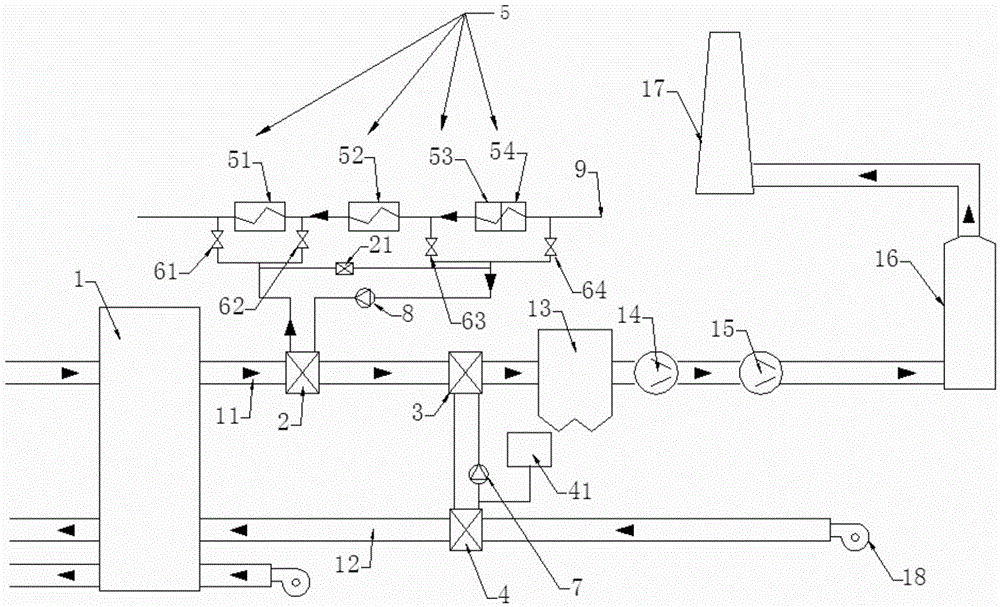
[0037] Such as figure 1 As shown, the emission reduction system for flue gas and dust of power plant boilers of the present invention includes an air preheater 1, a low-temperature heat exchanger 3, a dust collector 13, an induced draft fan 14, a booster fan 15, and a desulfurization tower connected in series to the boiler flue. 16 and the chimney 17 and including the air heat exchanger 4 and the secondary fan 18 connected in series outside the boiler flue, the output end of the secondary fan 18 is connected to the air preheater 1 through the air heat exchanger 4 The air side input end, the system also includes a first water pump 7, the heat exchange medium output end of the air heat exchanger 4 is connected to the heat exchange medium input end of the low temperature heat exchanger 3 through the first water pump 7, so The heat exchange medium output end of the low temperature heat exchanger 3 is connected to the heat exchange medium input end of the air heat exchanger 4;

[...


PUM


Abstract

The invention discloses a power station boiler flue gas and dust emission reduction system which comprises an air preheater, a cryogenic heat exchanger, a dust remover, a fan, a desulfurizing tower and a chimney, and further comprises an air heat exchanger and a secondary fan, wherein the air preheater, the cryogenic heat exchanger, the dust remover, the fan, the desulfurizing tower and the chimney are sequentially connected to a boiler flue in series, and the air heat exchanger and the secondary fan are sequentially connected to the outer side of the boiler flue in series. The output end of the secondary fan is connected with the air side input end of the air preheater through the air heat exchanger. The system further comprises a first water pump. The heat exchange medium output end of the air heat exchanger is connected with the heat exchange medium input end of the cryogenic heat exchanger through the first water pump, the heat exchange medium output end of the cryogenic heat exchanger is connected with the heat exchange medium input end of the air heat exchanger, and the outlet temperature of the cryogenic heat exchanger ranges from 80 DEG C to 100 DEG C. According to the power station boiler flue gas and dust emission reduction system, due to the fact that boiler flue gas emission temperature is lowered to be about flue gas acid dew point, the dust removing efficiency of the dust remover is effectively improved; in addition, flue gas emission waste heat is recycled to the maximum degree.

Description

technical field [0001] The invention relates to an emission reduction system for boiler flue gas and dust in a power plant. Background technique [0002] In recent years, the issue of climate deterioration has attracted more and more attention from the society, and reducing the dust content in the air has become increasingly important. The Ministry of Environmental Protection’s 2013 No. 14 Announcement requires that the dust removal facilities and desulfurization systems of thermal power plants in the main urban areas of 47 key cities must meet the special emission limit of 20mg / m after the dust removal facilities and desulfurization systems are transformed at the chimney inlet. 3 . At the same time, due to the increase in energy demand, the shortage of coal has brought a series of problems to the power industry. It has become the consensus of power generation enterprises to take effective measures to improve energy utilization and reduce power generation costs. [0003] ...

Claims


Application Information

Patent Timeline
Patent Type & Authority Patents(China)
IPC IPC(8): F22D1/38F23J15/02F28F19/02
Inventor 常海青袁朝张燕张灿郑木辉
Owner CHENGXIN GREEN INTEGRATION
Why Eureka
Try Eureka