Vacuum drying oven

A vacuum drying furnace and vacuum furnace technology, which is applied in the direction of drying solid materials, local agitation dryers, and static material dryers, etc., can solve the problems of difficult to completely remove moisture, reduce drying efficiency, and reduce drying effect, and achieve shortened drying time. The effect of baking time, avoiding dead angle of drying, and fast heat cycle

Inactive Publication Date: 2014-06-04
陈伟陵
View PDF0 Cites 22 Cited by
  • Summary
  • Abstract
  • Description
  • Claims
  • Application Information

AI Technical Summary

Problems solved by technology

Its heat transfer method is mainly heat radiation, and its drying process adopts the baking of the whole coil material. Since the coil material has many layers and the layers are tightly coiled, resulting in Moisture between layers is difficult to remove completely, resulting in too long baking time
[0003] In addition, because the vacuum drying oven adopts the traditional thermal radiation heating method, that is, heat transfer layer by layer, the outer layer material of the coil material is first heated up and then the inner layer material is contacted layer by layer to conduct heat, due to the temperature difference ( External heat and internal cooling) must greatly reduce the drying effect (long Baking time, poor drying effect), directly affect battery performance, and slow heat transfer speed, long heating time, greatly reduce drying efficiency, especially not suitable for batteries in the power battery industry Drying process of core roll material

Method used


Image

  • Vacuum drying oven
  • Vacuum drying oven
  • Vacuum drying oven

Examples


Embodiment Construction

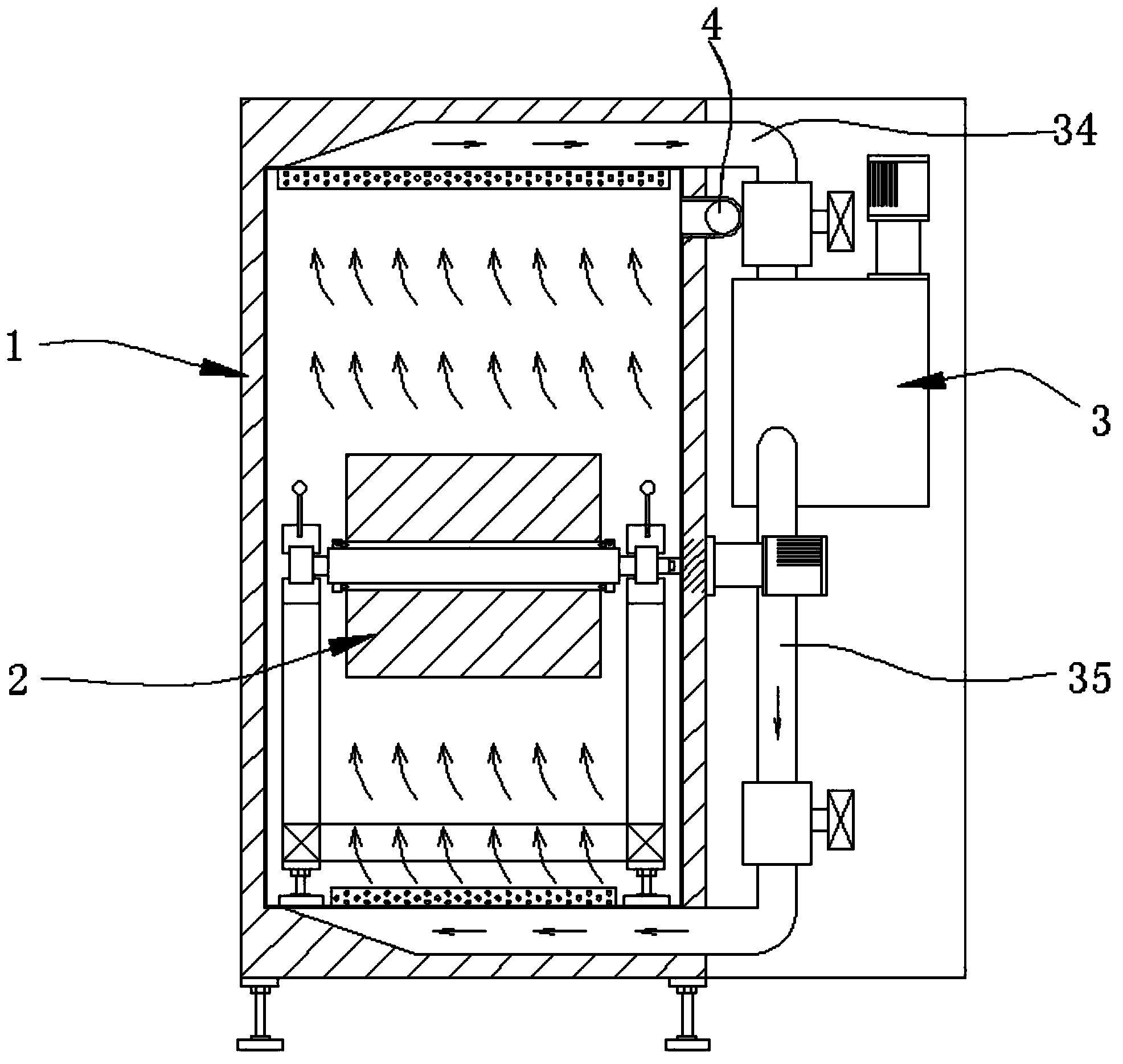
[0022] see Figure 1 to Figure 4 , a vacuum drying furnace provided in this embodiment, which includes a vacuum furnace body 1, in which at least one winding and unwinding mechanism 2 is provided, and on the outer wall of the vacuum furnace body 1 there is at least one conveyor Wind lighting device 3.

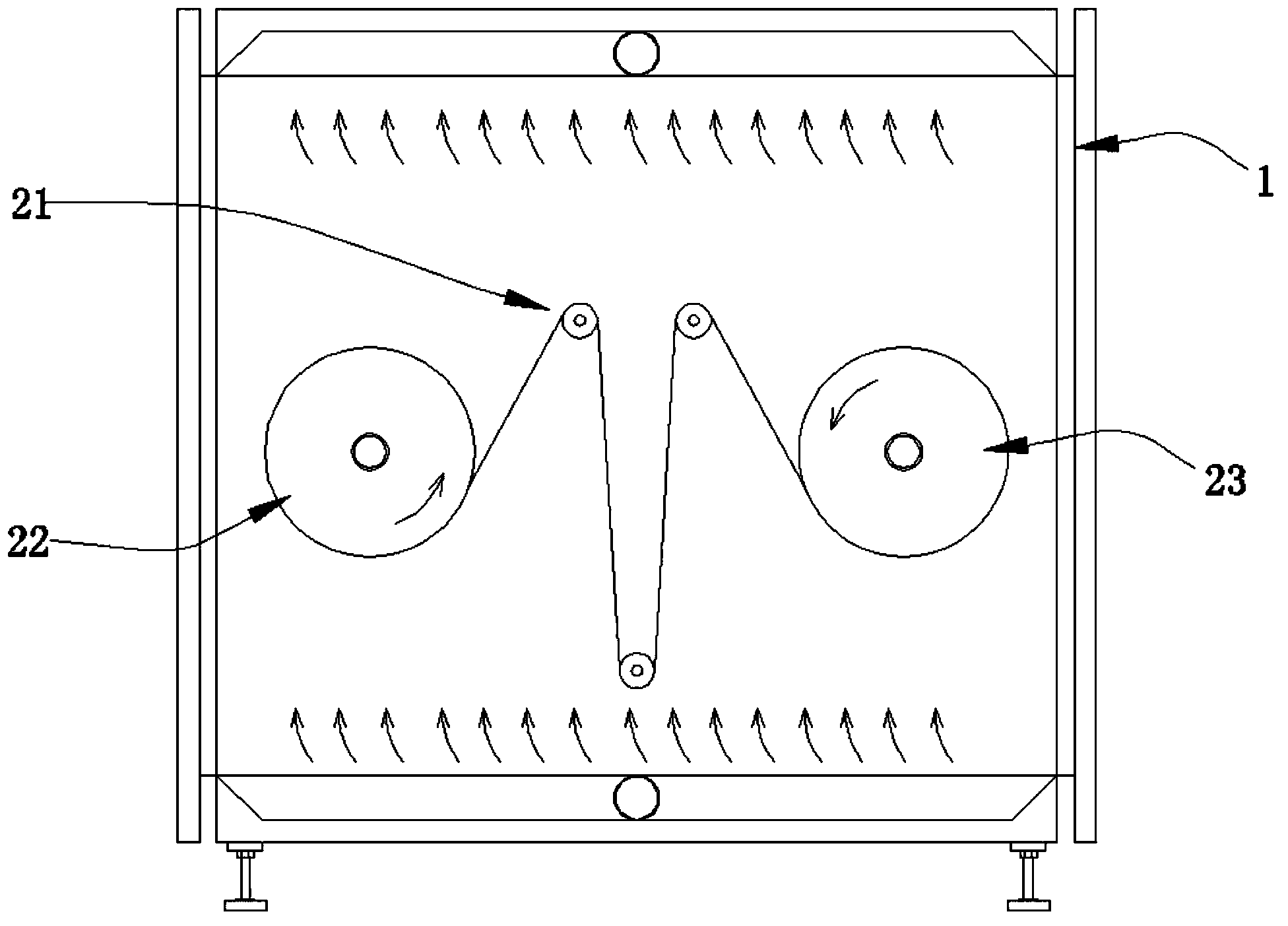
[0023] The rewinding and unwinding mechanism 2 includes a guide assembly 21, an unwinding assembly 22, and a rewinding assembly. The unwinding assembly 22 and the rewinding assembly are arranged at intervals and at the same level. The guide assembly 21 is arranged on the unwinding assembly. 22 and between the winding assembly.

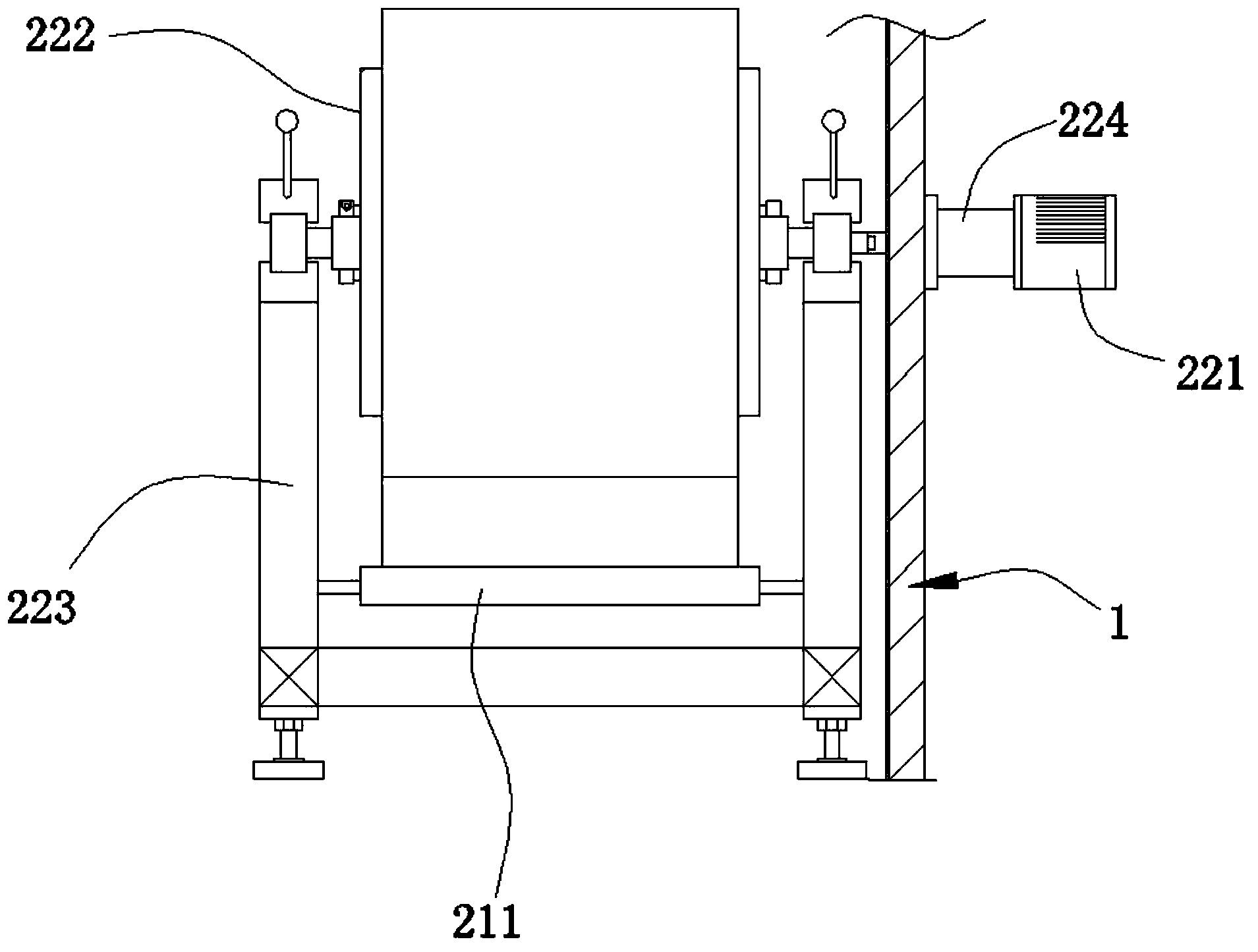
[0024] The uncoiling assembly 22 includes an uncoiling motor 221 and an uncoiling roller 222, the uncoiling roller 222 is arranged in the vacuum furnace body 1 through a bracket 223, and the uncoiling motor 221 is fixed in the vacuum furnace through an axial sealing device 224 The outer wall of the body 1, and the drive shaft of the unwinding motor 22...


PUM


Abstract

The invention discloses a vacuum drying oven. The vacuum drying oven comprises a vacuum oven body. The interior of the vacuum oven body is at least provided with a roll material winding and unwinding mechanism. The outer sidewall of the vacuum oven body is at least provided with a wind-powered light emitting device. The vacuum drying oven is simple in structure and reasonable in design; roll materials in the vacuum oven body can be unwound for baking through the roll material winding and unwinding mechanism, so that baking time is effectively shortened, and baking quality is improved. Meanwhile, hot air is delivered to an inner cavity of the vacuum oven body through the wind-powered light emitting device to form a dynamic loop for circulation heating, the heat cycle is fast, the temperature rise rate of the vacuum drying oven can be increased, good temperature uniformity can also be acquired, so that a drying effect is further improved, and product quality is guaranteed. Moreover, nitrogen which has a drying effect can further be led in through a nitrogen pipe, water is pumped out through a vacuum tube, and therefore a breath type drying effect is formed. In this way, drying time is substantially shortened, production efficiency is enhanced, and the vacuum drying oven can be widely popularized and especially applicable to the power battery industry.

Description

technical field [0001] The invention relates to a drying furnace, in particular to a vacuum drying furnace. Background technique [0002] The structure of the current conventional vacuum drying oven is that a number of heat pipes are arranged on the outer wall of the cavity, and heat is transferred through the side wall of the cavity, thereby heating the coil material. Its heat transfer method is mainly heat radiation, and its drying process adopts the baking of the whole coil material. Since the coil material has many layers and the layers are tightly coiled, resulting in The moisture between the layers is difficult to completely remove, resulting in an excessively long baking time. [0003] In addition, because the vacuum drying oven adopts the traditional thermal radiation heating method, that is, heat transfer layer by layer, the outer layer material of the coil material is first heated up and then the inner layer material is contacted layer by layer to conduct heat, du...

Claims


Application Information

Patent Timeline
Patent Type & Authority Applications(China)
IPC IPC(8): F26B9/00F26B7/00
Inventor 陈伟陵
Owner 陈伟陵
Why Eureka
Try Eureka