Target displacement vector measuring device and method based on laser tracker point-by-point calibration

A technology of laser tracker and target displacement, which is applied to measurement devices, optical devices, instruments, etc., can solve the problems of low accuracy of measurement results, and achieve the effect of improving detection accuracy, solving detection problems, and improving use efficiency.

Active Publication Date: 2014-06-04
HARBIN INST OF TECH
View PDF6 Cites 17 Cited by
  • Summary
  • Abstract
  • Description
  • Claims
  • Application Information

AI Technical Summary

Problems solved by technology

[0011] The purpose of the present invention is to solve the problem of low accuracy of the measurement results in the detection method of the target micro-displacement in the existing visual detection and measurement system, and to provide a target displacement vector measurement device and method based on the point-by-point calibration of the laser tracker

Method used


Image

  • Target displacement vector measuring device and method based on laser tracker point-by-point calibration
  • Target displacement vector measuring device and method based on laser tracker point-by-point calibration
  • Target displacement vector measuring device and method based on laser tracker point-by-point calibration

Examples


specific Embodiment approach 1

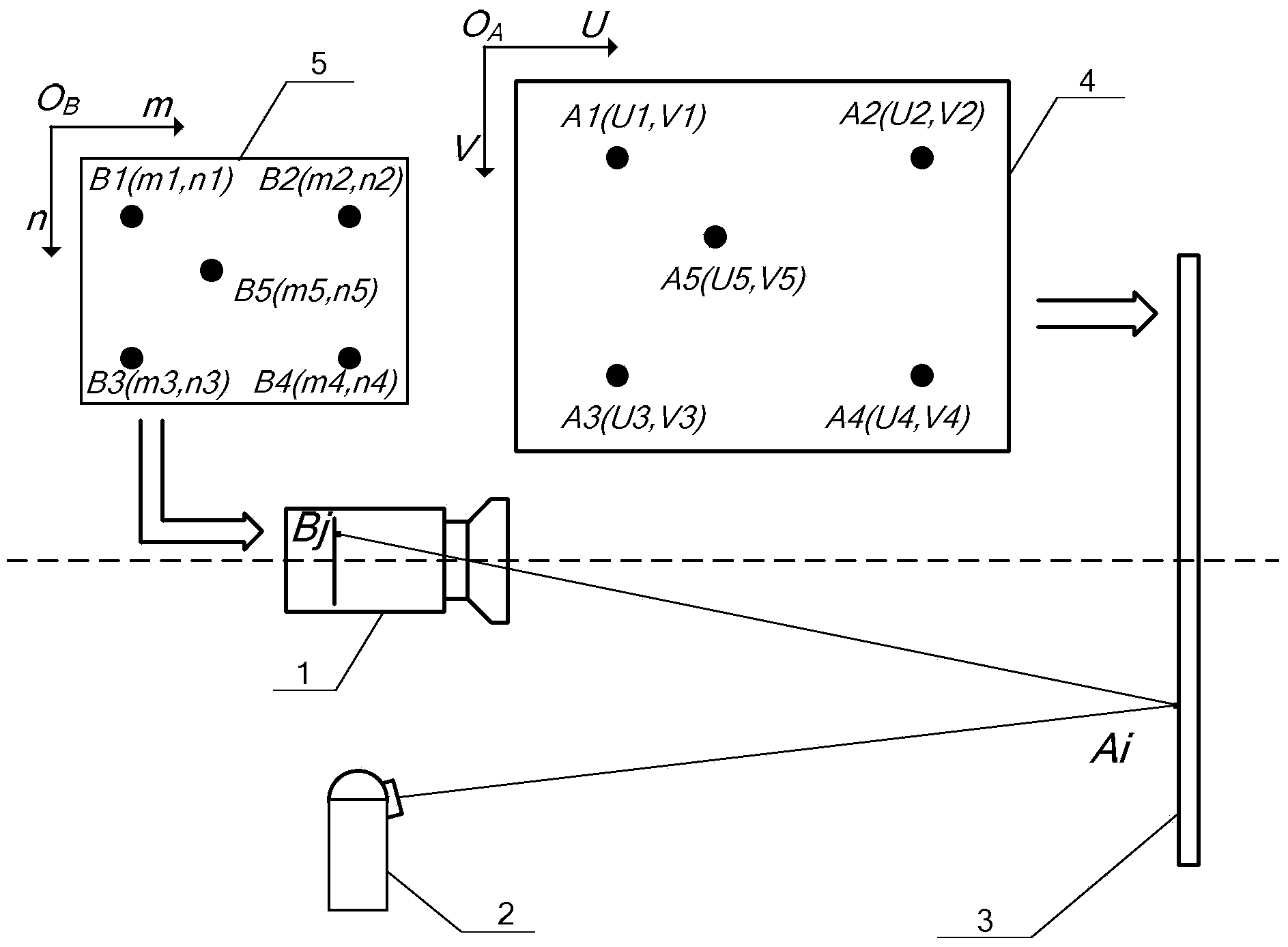
[0047] Specific implementation mode one: the following combination figure 1 Describe this embodiment, the target displacement vector measuring device based on laser tracker point-by-point calibration described in this embodiment, it comprises high-speed CCD camera 1, laser tracker 2 and diffuse reflection projection screen 3, target object is on diffuse reflection projection screen 3 move up;

[0048] The high-speed CCD camera 1 is used to image the target marking point on the diffuse reflection projection screen 3 , and the laser tracker 2 is used to measure the coordinates of the target marking point on the diffuse reflection projection screen 3 .

[0049] In this embodiment, the spatial ranging range of the laser tracker 2 is not less than 50m, the angle measuring range is better than 100° in the vertical direction, better than 180° in the horizontal direction, and the positioning accuracy is better than 20μm+5μm / m.

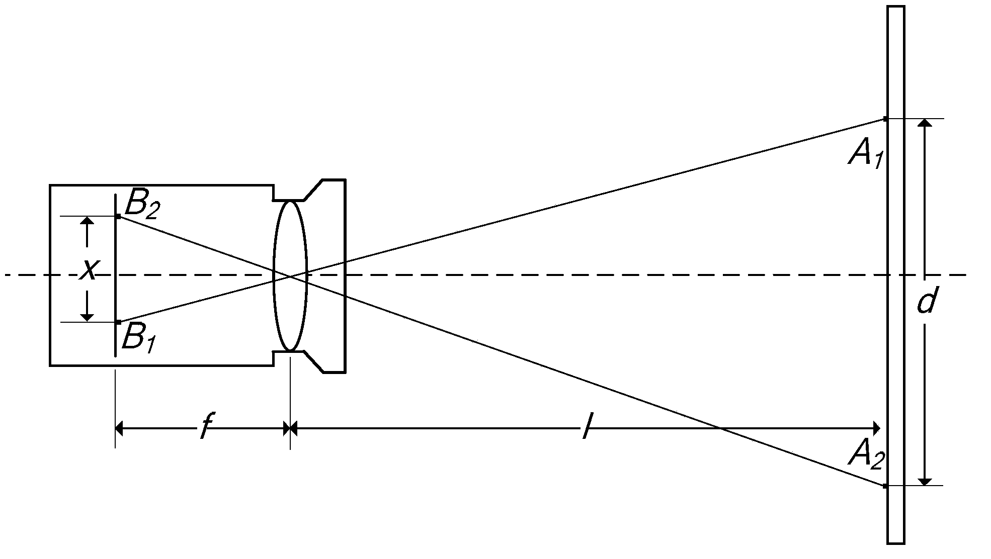
[0050] The lens focal length of the high-speed CCD cam...

specific Embodiment approach 2

[0052] Specific Embodiment 2: This embodiment will further explain Embodiment 1. The diffuse reflection projection screen 3 in this embodiment is a square formed by splicing two pieces of 1000mm×500mm×3mm frosted glass. The diffuse reflection projection screen 3 Spray black paint on the back.

[0053] In this embodiment, the diffuse reflection projection screen 3 has a surface area of ​​1m×1m, and the black paint on its back is used to eliminate secondary reflection. The flatness of the frosted glass is required to be better than 0.2mm, the joint between two pieces of frosted glass is less than 0.5mm, the overall flatness of the diffuse reflection projection screen 3 is better than 0.5mm, and the verticality to the ground is better than 0.1°.

specific Embodiment approach 3

[0054] Specific implementation mode three: the following combination figure 1 Describe this embodiment, the measurement method based on the above-mentioned target displacement vector measuring device based on laser tracker point-by-point calibration described in this embodiment, it includes the following steps:

[0055] Step 1: Set a point A1 on the diffuse reflection projection screen 3 as the target calibration point, and the coordinate value of the target calibration point A1 on the projection screen coordinate system 4 obtained by the laser tracker 2 is A1 (U1, V1);

[0056] Step 2: keep the target calibration point A1 fixed, use the high-speed CCD camera 1 to image the target calibration point A1, obtain the corresponding conjugate point B1 of the target calibration point A1 on the image plane of the high-speed CCD camera 1, and use the high-speed CCD camera 1 to obtain the corresponding conjugate point B1 of the target calibration point A1. After the image processing of...


PUM


Abstract

The invention provides a target displacement vector measuring device and method based on laser tracker point-by-point calibration, and belongs to the technical field of infinitesimal displacement measurement. The target displacement vector measuring device and method aim to solve the problem that measurement results obtained through a method for detecting target infinitesimal displacement through an existing visual-inspection measuring system are low in accuracy. The device comprises a high-speed CCD video camera, a laser tracker and a diffuse reflection projection screen, wherein a target object moves on the diffuse reflection projection screen. According to the method, first, a corresponding relation look-up table is established based on the principle that imaging points of target object calibration points and target object calibration points acquired through the laser tracker are conjugated; then, the high-speed CCD video camera is used for sequentially imaging screen light spots of the target object, a conjugate point of a target object projection point is acquired, and the coordinate value of the target object projection point on a projection screen coordinate system is obtained through table look-up or a resolving method combining table look-up with bilinear interpolation. The target displacement vector measuring device and method based on laser tracker point-by-point calibration are used for measuring a target displacement vector.

Description

technical field [0001] The invention relates to a target displacement vector measuring device and method based on point-by-point calibration of a laser tracker, and belongs to the technical field of micro-displacement detection. Background technique [0002] Micro-displacement detection technology is of great significance in the field of modern precision measurement. Through the high-precision measurement of micro-displacement, combined with the structural parameters of the spatial layout, precision measurement of a series of important parameters such as angle, speed, straightness, and flatness can be completed. . At the same time, it can also be used to evaluate the control accuracy of various existing instruments, and can detect the movement accuracy of the target object in space. [0003] At present, the displacement measurement technology with high precision in the world is dual-frequency laser interferometry, and the displacement precision measured by it is at the nano...

Claims


Application Information

Patent Timeline
Patent Type & Authority Applications(China)
IPC IPC(8): G01B11/03
Inventor 陈刚孟繁擘郭玉波叶东于潇宇吕旭冬
Owner HARBIN INST OF TECH
Why Eureka
Try Eureka