Dynamic driving system adopting servo force

A technology of drive system and servo drive, which is applied in the testing of measuring devices, instruments, and mechanical components, etc., can solve the problems of low precision of dynamic output force, poor ability of PID control to resist external interference, etc., and achieve compact structure, small volume, The effect of dynamic high-precision loading

Inactive Publication Date: 2014-06-04
INST OF MACHINERY MFG TECH CHINA ACAD OF ENG PHYSICS
View PDF7 Cites 17 Cited by
  • Summary
  • Abstract
  • Description
  • Claims
  • Application Information

AI Technical Summary

Problems solved by technology

[0004] In order to solve the problems of poor anti-interference ability of PID control and low accuracy of dynamic output force, the present invention provides a dynamic servo force drive system, which is based on compression springs and servo motors, has a large stroke, a wide range of output force, and can realize dynamic loaded features

Method used


Image

  • Dynamic driving system adopting servo force
  • Dynamic driving system adopting servo force
  • Dynamic driving system adopting servo force

Examples


Embodiment 1

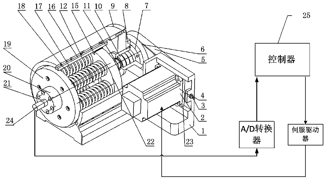
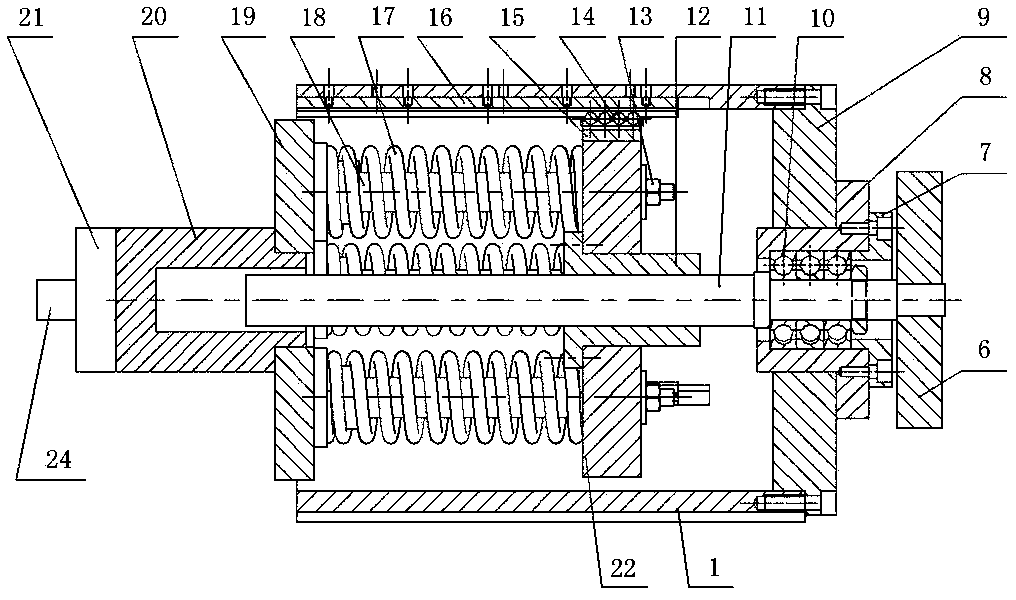
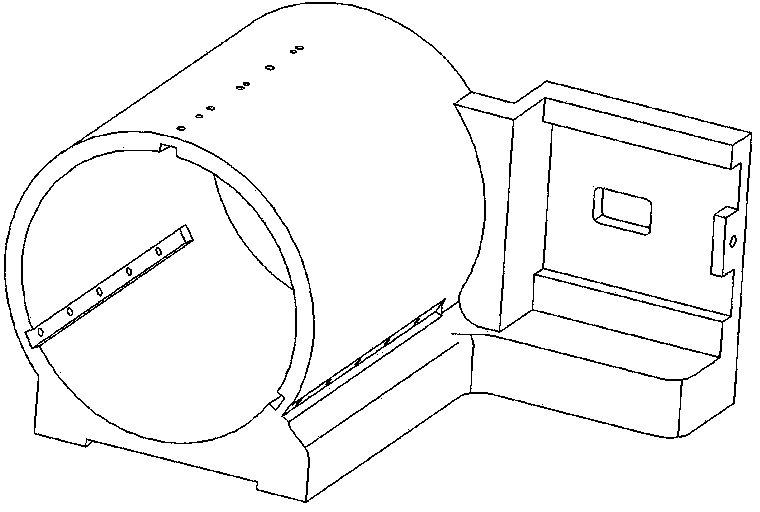
[0033] figure 1 It is a structural schematic diagram of the mechanical body in the present invention, figure 2 It is a sectional view of the mechanical body part in the present invention, image 3 Schematic diagram of the base structure of the mechanical body part in the present invention, Figure 4 It is a structural schematic diagram of the front loading disk of the mechanical body part in the present invention, Figure 5 It is a structural schematic diagram of the guide rod of the machine body part in the present invention. Figure 6 It is a system block diagram of the present invention, Figure 7 It is the dynamic force servo drive system of the present invention under the sinusoidal reference force, without the adaptive sliding mode control response curve and the tracking error curve of the disturbance observer, Figure 8 It is the dynamic servo driving force system of the present invention under the sinusoidal reference force, the adaptive sliding mode control respo...

Embodiment 2

[0064] The structure of this embodiment is the same as that of Embodiment 1, the difference is that: the driving method of the ball screw can be directly driven by the servo motor through the coupling and the ball screw. The ball screw can be realized by adopting a trapezoidal screw and a nut pair. A guide key can be used between the rear loading plate and the support to replace the rolling element assembly. The bearing set is a bearing set containing thrust ball bearings or cylindrical roller thrust bearings. The controller adopts single-chip microcomputer, DSP processor or industrial control computer.


PUM


Abstract

The invention provides a dynamic driving system adopting servo force. The dynamic driving system adopting servo force comprises a mechanical body, a motor, a force sensor, an A / D converter, a controller and a servo driver, wherein the mechanical body comprises a front loading disc and a rear loading disc, a plurality of springs are arranged between the front loading disc and the rear loading disc, and the rear loading disc is fixed to a nut of a ball screw in the mechanical body; the motor can drive the ball screw, and the ball screw drives the rear loading disc, so that the front loading disc and the rear loading disc move relatively to compress the springs to enable loading force to be generated. During loading, the controller controls the servo driver to drive the motor according to set force and signals of the force sensor, and thus accurate loading according to the set force can be achieved. According to the dynamic driving system adopting servo force, due to the fact that the compression springs which are connected in parallel are adopted, output force is increased in a multiplied mode; due to the fact that the compression springs are fixed to the loading discs which can roll along a fixed support and the stroke is determined by the length of the ball screw, the dynamic driving system has the advantages that the output force is large and the stroke is large; due to the fact that a self-adaptive sliding-mode control algorithm with a disturbance observer involved is adopted by the controller, dynamic high-precision loading can be achieved under the condition that external disturbance exists.

Description

technical field [0001] The invention relates to a dynamic servo drive system. It can be applied to the application of load spectrum, working condition simulation, static stiffness test, etc. in reliability tests of functional components such as CNC machine tool spindles and guide rails. It can also be applied to loading tests that require large loading forces and large strokes. Background technique [0002] In the reliability evaluation of CNC machine tools, it is necessary to apply loads to the spindle according to a certain load spectrum. In order to simulate the actual running state of the machine tool, the loading device not only needs to exert a certain amount of force on the spindle, but also be able to simulate the relative movement between the spindle and the table. Usually it can be loaded by air cylinder or hydraulic cylinder. But the former needs an air source; the latter needs a hydraulic station, which is noisy and easy to pollute. Chinese patent (Patent No...

Claims


Application Information

Patent Timeline
Patent Type & Authority Applications(China)
IPC IPC(8): G01M13/00
Inventor 舒强胡秋夏仰球汪俊文张日升廖正菊米良
Owner INST OF MACHINERY MFG TECH CHINA ACAD OF ENG PHYSICS
Why Eureka
Try Eureka