Radio frequency identification label and manufacturing method thereof
A radio frequency identification tag and radio frequency technology, applied in the field of radio frequency identification electronic tags and their preparation, can solve problems such as loss, achieve good anti-counterfeiting performance, good fragile performance, and improve the effect of yield
- Summary
- Abstract
- Description
- Claims
- Application Information
AI Technical Summary
Problems solved by technology
Method used
Image
Examples
preparation example Construction
[0028] The preparation method of the radio frequency identification tag of the present invention includes the following steps:
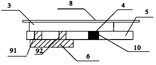
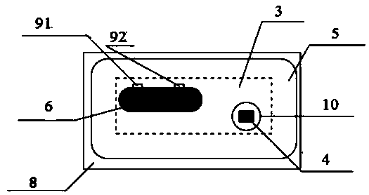
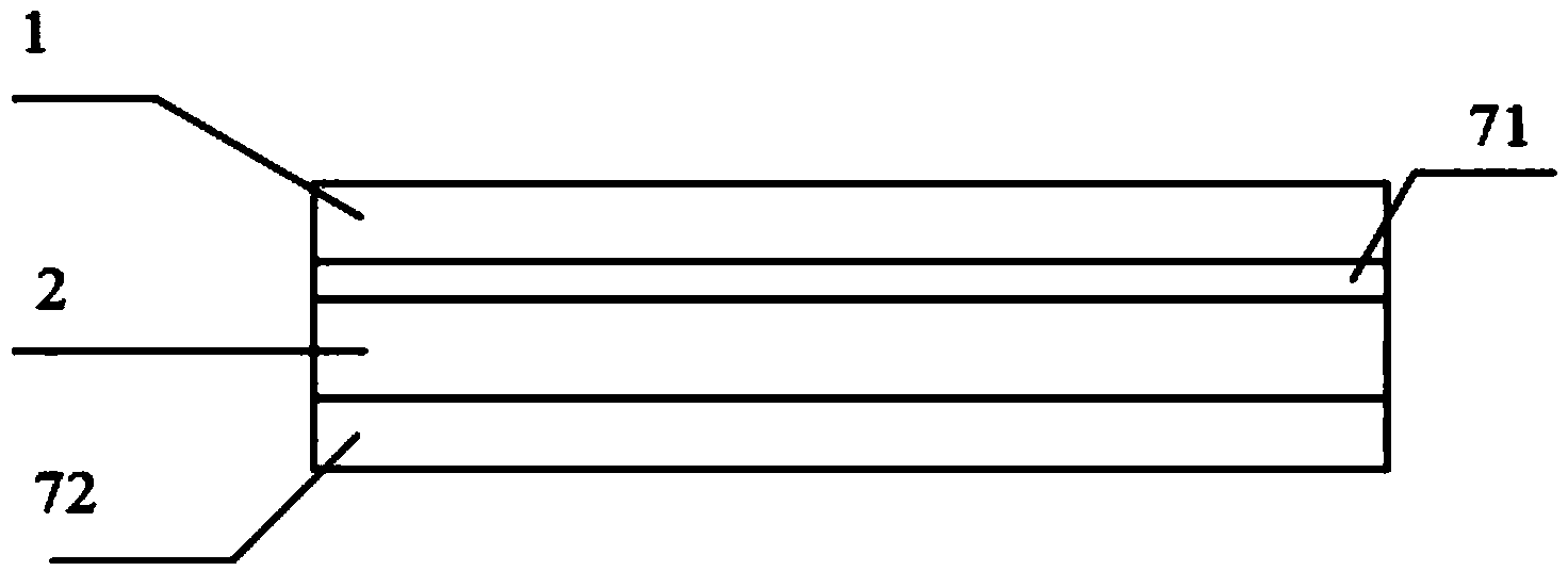
[0029] (1) Coat the release material on the support material such as polyester material to form the release layer 8. Dry it at 80-120℃ for 1 to 5 minutes, preferably infrared drying, and then prepare the wireless layer on the release layer 8. Radio frequency identification antenna 3;
[0030] RFID antenna 3 can use "Study on Screen Printing Process Parameters of Smart Tag Antenna", "Electronic Tag RFID Conductive Ink and Printed Antenna Technology", "Three Manufacturing Methods of RFID Antenna", "Gravure Etching Method to Manufacture RFID Antenna" "", "The principle, application and prospect of electroless copper plating", "Introduction to vacuum aluminum plating process" and other methods reported in the literature;
[0031] (2) On the radio frequency identification antenna 3 obtained in step 1, an isolation layer 5 is printed, and at the same time, the p...
Embodiment 1
[0037] (1) Coat the release material polystyrene with polyester material PET (polyethylene terephthalate) as the support layer, dry at 110°C for 3 minutes, and use infrared drying to form the release layer 8, and then The aluminum etching antenna is prepared by etching on the surface of the release layer 8, and the preparation method reported in the literature such as "Making RFID Antenna by Gravure Etching Method" can be used;
[0038] (2) On the etched antenna formed in step (1), an isolation layer of melamine alkyd resin with insulating properties is printed with a thickness of 30 microns; at the same time, the printed isolation layer has holes 8C that do not cover the chip and do not cover the bridge The small holes of holes 91 and 92; the area of chip hole 10 is larger than the chip area, which is 50mm 2 ; The area of the bridge holes 91 and 92 are both 30mm 2 Except for the bridge holes 91, 92 and the chip hole 10, the isolation layer covers the rest of the antenna;
[00...
Embodiment 2
[0043] (1) Use polyester material PET (polyethylene terephthalate) as support layer, coat release material silicone release agent, dry at 120°C for 5 minutes, and use infrared drying to form release layer 8 , And then use the screen printing method to prepare the printed antenna on the surface of the release layer. The preparation method reported in the literature such as "Electronic Tag RFID Conductive Ink and Printed Antenna Technology" can be used;
[0044] (2) On the printed antenna formed in step (1), an isolating layer epoxy resin with insulating properties is printed with a thickness of 40 microns; at the same time, the printed isolating layer has holes 10 that do not cover the chip and do not cover the bridge Small holes of holes 91 and 92; the area of chip hole 10 is larger than the chip area, which is 30mm 2 ; The area of bridge holes 91 and 92 are both 40mm 2 Except for the bridge holes 91, 92 and the chip hole 10, the isolation layer covers the rest of the antenna;...
PUM
| Property | Measurement | Unit |
|---|---|---|
| Thickness | aaaaa | aaaaa |
| Area | aaaaa | aaaaa |
Abstract
Description
Claims
Application Information
 - R&D
- Intellectual Property
- Life Sciences
- Materials
- Tech Scout
- Unparalleled Data Quality
- Higher Quality Content
- 60% Fewer Hallucinations
Browse by: Latest US Patents, China's latest patents, Technical Efficacy Thesaurus, Application Domain, Technology Topic, Popular Technical Reports.
© 2025 PatSnap. All rights reserved.Legal|Privacy policy|Modern Slavery Act Transparency Statement|Sitemap|About US| Contact US: help@patsnap.com


