Adjustable reactive power compensator for power networks

A power compensator, power technology, applied in the system field, to achieve the effect of easy surge voltage

Active Publication Date: 2014-06-04
HITACHI ENERGY SWITZERLAND AG
View PDF7 Cites 2 Cited by
  • Summary
  • Abstract
  • Description
  • Claims
  • Application Information

AI Technical Summary

Problems solved by technology

[0010] Another disadvantage of the three-phase system is that due to the high voltage between th

Method used


Image

  • Adjustable reactive power compensator for power networks
  • Adjustable reactive power compensator for power networks

Examples


Embodiment Construction

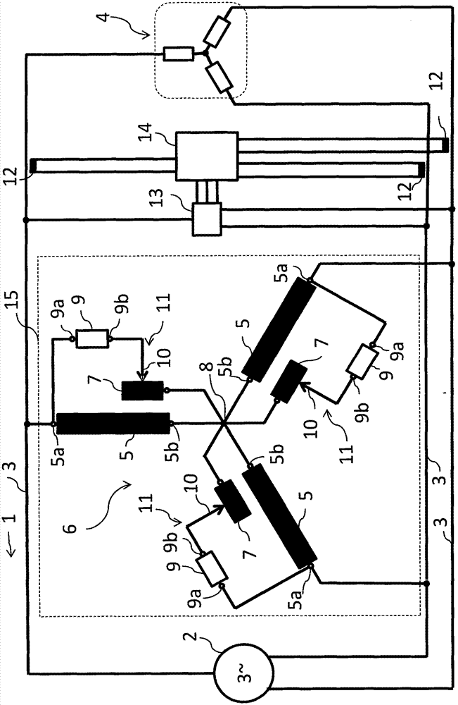
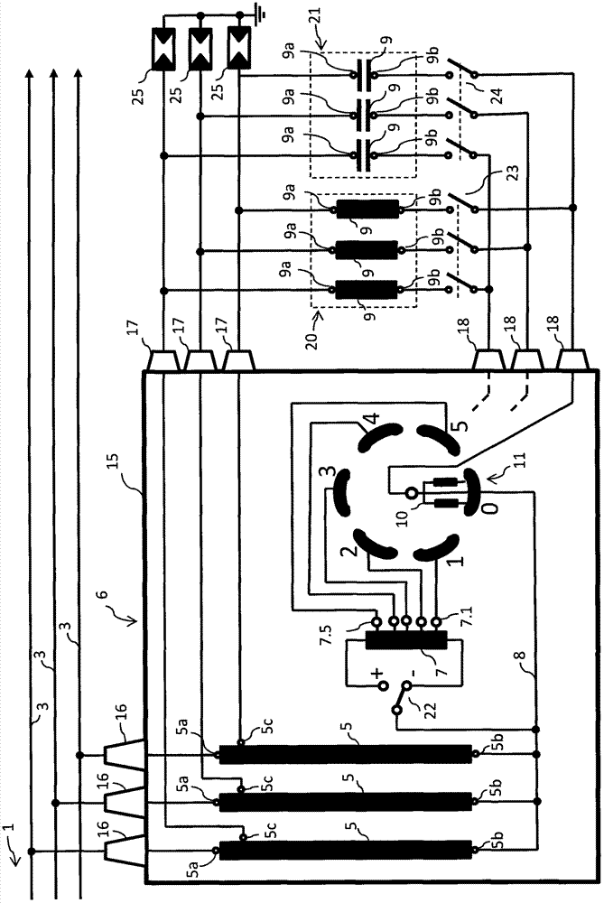
[0018] figure 1 The main circuit diagram of the reactive power compensator used in the three-phase grid according to the present invention is shown. The transmission or distribution network 1 is powered by an AC power source 2. The power supply network has a live conductor 3 for each three phase to supply power to the load 4. The autotransformer 6 includes a pair of primary windings 5 ​​and secondary windings for each phase. The first end 5a of the primary winding 5 of the autotransformer 6 is connected to the wire 3. The second ends 5b of the primary winding 5 are connected to each other in a star shape to form a star point 8. The secondary winding 7 of the autotransformer is connected to the star point 8. The reactive power compensator contains at least one reactive component 9 for each pair of primary and secondary windings. The inductor is used as a reactive component 9 to compensate for capacitive reactive power, and the capacitor is used to compensate for inductive re...


PUM


Abstract

A reactive power compensator for an electric power transmission or distribution network comprising reactive components (9) for compensating reactive power and an autotransformer (6) with pairs of primary windings (5) and secondary windings (7), the primary windings for connecting the autotransformer (6) to power lines (3) and the secondary windings (7) for connecting the autotransformer (6) to second poles (9b) of the reactive components (9), the primary windings (5) being star-connected to form a star-point (8) and the secondary windings (7) being connected to the star-point (8) of the autotransformer (6).

Description

Technical field [0001] The present invention relates to a reactive power compensator used in power transmission or distribution networks, and more particularly to a system in which the voltage on a reactor or capacitor bank is regulated by an autotransformer. Background technique [0002] Depending on the characteristics of the total load in the power transmission or distribution network, capacitive or inductive reactive power is usually present. Overhead lines themselves represent inductive reactance, but underground cables, which are now on the rise, create capacitive reactive power for power networks. Usually in a commercial contract, a fixed window is allowed to be used for reactive power [Q], for example about the calculated maximum 4% capacitive or 16% inductive power of the effective power [P]. [0003] The reactive power compensation device is to keep the relevant reactive power within the required window and keeping it as low as possible will reduce the cost of reactive p...

Claims


Application Information

Patent Timeline
IPC IPC(8): H02J3/18
CPCH02J3/1878H02J3/16Y02E40/34H02J3/1821H01F21/12H01H9/0005H01F29/02H01F38/02H02J3/1828Y02E40/30H02J3/18
Inventor T·蒂奥米斯托
Owner HITACHI ENERGY SWITZERLAND AG
Why Eureka
Try Eureka