neurosurgical equipment

A technology of shunt equipment and slender tubes, which can be used in medicine devices, wound drainage devices, and other medical devices, and can solve problems such as blockage, and achieve the effect of reducing the chance of shunt blockage and reducing the need

Active Publication Date: 2016-03-09
RENISHAW (IRELAND) LTD
View PDF5 Cites 0 Cited by
  • Summary
  • Abstract
  • Description
  • Claims
  • Application Information

AI Technical Summary

Problems solved by technology

[0003] Thousands of many ventricular shunt systems are implanted each year, but a significant number of these become clogged within a relatively short period of time

Method used


Image

  • neurosurgical equipment
  • neurosurgical equipment
  • neurosurgical equipment

Examples


Embodiment Construction

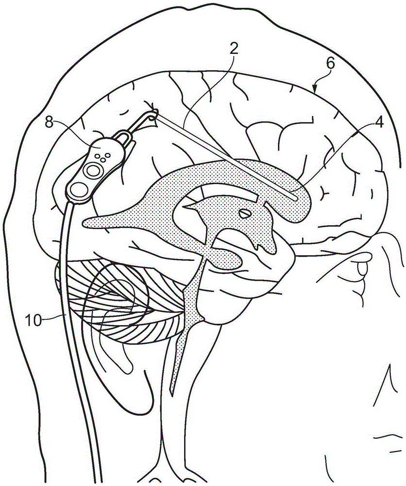
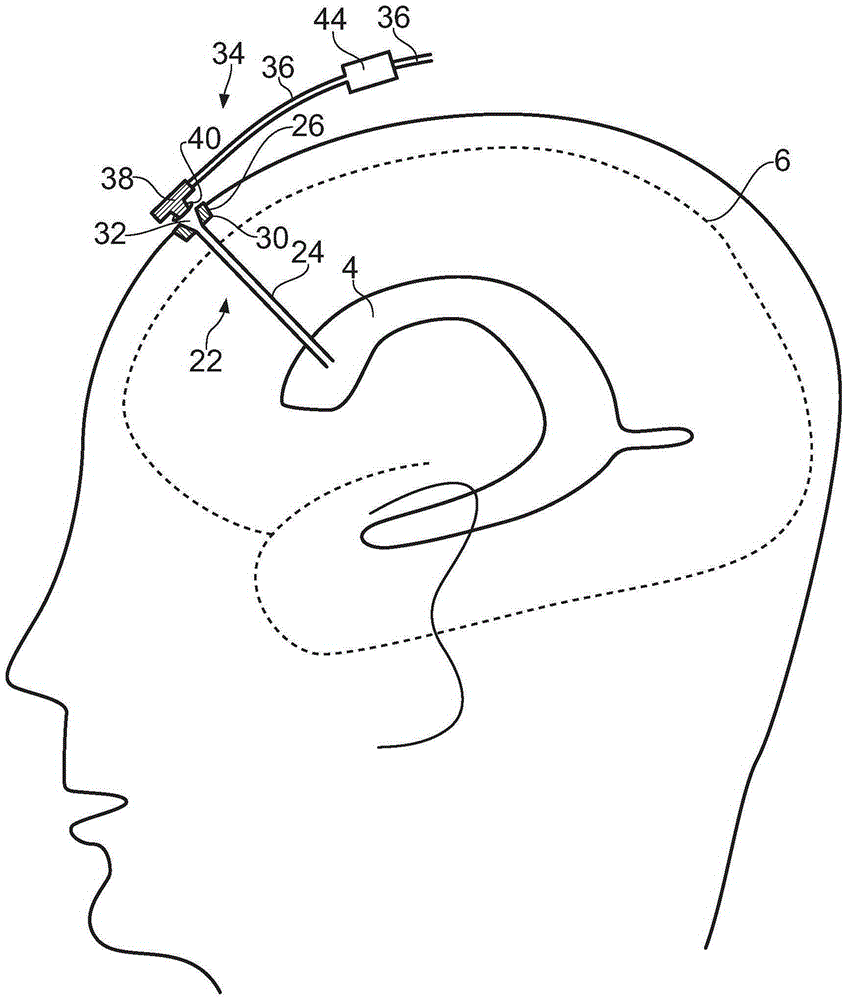
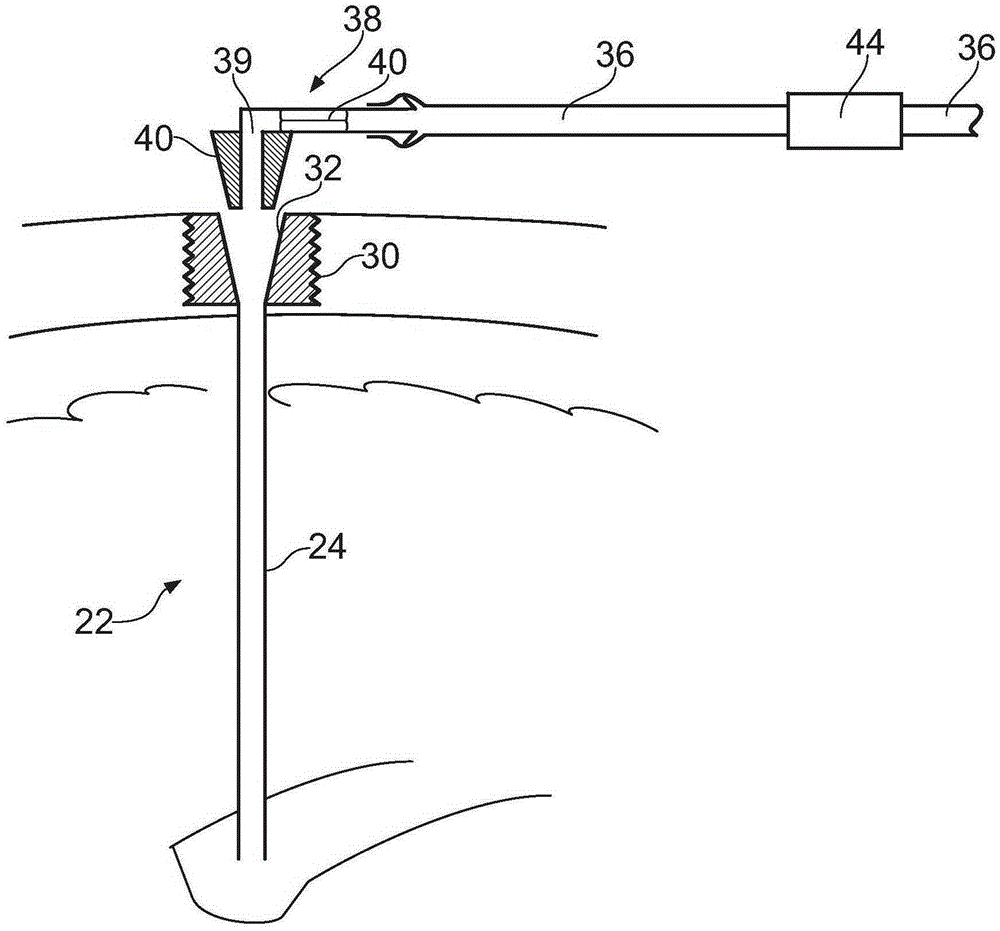
[0035] Referring to FIG. 1 , a prior art ventricular shunt device is shown. The ventricular shunt device comprises a cerebral catheter device 2 which takes the form of a length of elastic silicone tubing. The distal portion of the brain catheter device 2 is placed within the lateral ventricle 4 of the brain 6 and includes a plurality of orifices in its side wall (not shown) for collecting CSF.

[0036] A typical procedure for implanting the catheter device 2 involves making an incision in the scalp and forming a burr hole (typically 10mm to 15mm in diameter) through the skull. An elongated rod or probe is then manually inserted into the brain by the surgeon and guided into the lateral ventricle using external anatomical landmarks for guidance. The probe is then withdrawn and the distal portion of the brain catheter device 2 is pushed along the pathway already formed in the brain tissue until its distal portion reaches the lateral ventricle.

[0037] The proximal end of the c...


PUM


Abstract

A cerebral catheter device for draining fluid from the brain of a patient is described. The device may be used as part of a ventricular shunt system. The device includes an elongate tube for insertion into the brain of a patient to a vicinity of a desired target. A head is attached to the elongate tube that has a passageway in fluid communication with a lumen of the elongate tube. Formations are provided on the external surface of the head for securing the head in a hole formed in the skull of a patient. The head further includes a first fluid connector portion that is attachable to an associated drainage catheter device. This allows fluid communication to be established between the lumen of the elongate tube and a drainage catheter device via the passageway of the head.

Description

technical field [0001] The present invention relates to brain shunt devices. In particular, the present invention relates to a cerebral catheter device and related equipment suitable for draining fluid from the ventricles of the brain (eg, for the treatment of hydrocephalus) or from cysts. Background technique [0002] Shunt implantation to drain cerebrospinal fluid (CSF) from the lateral ventricles of the brain is a well-established neurosurgical procedure. This surgery is usually done to treat hydrocephalus. A typical ventricular shunt device includes an elongated flexible catheter formed of a silicone material. To insert this ventricular shunt device, a hole is drilled in the skull and a pathway is made through the brain tissue to the lateral ventricles. Pathway formation is usually performed by hand using long rigid probe elements. A long, thin silicone catheter is then inserted along the preformed pathway into the lateral ventricle of the brain, from which fluid is ...

Claims


Application Information

Patent Timeline
Patent Type & Authority Patents(China)
IPC IPC(8): A61M27/00A61M39/02
CPCA61M27/006A61M39/0247A61M2025/0213A61M2039/025A61M2039/0282
Inventor 史蒂文·斯特里特菲尔德·吉尔
Owner RENISHAW (IRELAND) LTD
Why Eureka
Try Eureka