
Switching power supply circuit with protective function

A switching power supply circuit and protection function technology, applied in emergency protection circuit devices, output power conversion devices, electrical components, etc., can solve the problems of switching power supply device damage, fire, smoke, etc. Effects of damage accidents

Inactive Publication Date: 2014-06-04
DATA I O
View PDF4 Cites 4 Cited by
  • Summary
  • Abstract
  • Description
  • Claims
  • Application Information

AI Technical Summary

Problems solved by technology

Therefore, if you continue to use it beyond the lifespan, the switching power supply device will be damaged due to the deterioration of the electrolytic capacitor, and sometimes there is a risk of accidents such as smoke and fire.

Method used


Image

  • Switching power supply circuit with protective function
  • Switching power supply circuit with protective function
  • Switching power supply circuit with protective function

Examples


Embodiment Construction

[0029] Embodiments of the present invention will be described below with reference to the drawings.

[0030] 1st embodiment

[0031] First, the circuit configuration of the first embodiment of the present invention will be described.

[0032]

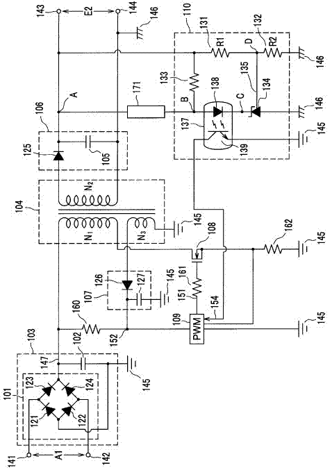
[0033] figure 1 It is a circuit diagram showing a schematic configuration of the first embodiment of the switching power supply circuit with protection circuit of the present invention.

[0034] exist figure 1 Among them, the primary-side rectifier circuit 101 uses a bridge circuit structure of diodes 121-124 to perform full-wave rectification on the AC power (AC voltage A1) input from the AC power supply terminals 141 and 142, and outputs DC power including ripples to the primary between the DC terminal 147 on the primary side and the ground wire 145 on the primary side.

[0035] The primary-side electrolytic capacitor 102 is connected between the primary-side DC terminal 147 and the primary-side ground 145 , and smoothes the DC ...


PUM


Abstract

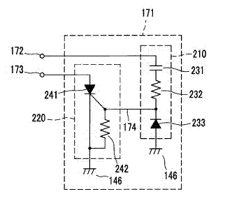
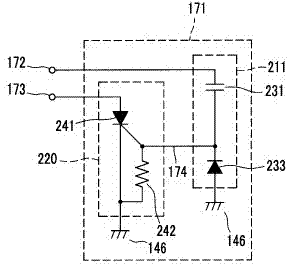
A switching power supply circuit comprises: a transformer (104) having a primary winding (N1), a secondary winding (N2), and a tertiary winding (N3); a primary side rectification smoothing circuit (103) for converting an AC power to a DC power and smoothing the DC power; a secondary side rectification smoothing circuit (106) for smoothing secondary side power; a tertiary side rectification smoothing circuit (107) for smoothing the power in the tertiary winding; a switching circuit (108) for opening and closing the primary winding circuit; a pulse width control circuit (109) for controlling the opening and closing of the switching circuit; an output error detection circuit (110) for detecting the deviation between a secondary side DC output voltage and a reference voltage; and a ripple voltage detection control circuit (171) for detecting the ripple voltage of the secondary side DC output voltage and performing control for stopping the output error detection circuit. The output of the output error detection circuit is stopped by a stop control signal from the ripple voltage detection control circuit and a drive signal input to the switching circuit is stopped, resulting in the stop of the operation of the switching power supply circuit.

Description

technical field [0001] The present invention relates to a technique for detecting deterioration of an electrolytic capacitor for a smoothing circuit included in a switching power supply device, and preventing damage accidents before they occur. Background technique [0002] In switching power supply devices, electrolytic capacitors used in smoothing circuits gradually deteriorate due to repeated charging and discharging with large currents and use over time. Therefore, if you continue to use it beyond its lifespan, the switching power supply will be damaged due to deterioration of the electrolytic capacitor, and there may be a risk of accidents such as smoke and fire. [0003] In addition, various techniques for detecting and counteracting degradation of electrolytic capacitors have also been studied by developing circuits in switching power supply circuits. [0004] Patent Document 1 discloses the detection of occurrence of deterioration of electrolytic capacitors based on...

Claims


Application Information

Patent Timeline
Patent Type & Authority Applications(China)
IPC IPC(8): H02M3/28H02H7/20
CPCH02M3/33523H02M1/32H02H7/1255H02H7/1213
Inventor 坂孝志
Owner DATA I O
Learn More