Control system for air source heat pump drying production line

An air source heat pump and control system technology, applied in heat pumps, refrigerators, refrigeration components, etc., can solve problems such as large power consumption, and achieve the effects of energy saving, convenient operation, and intelligent operation

Inactive Publication Date: 2014-06-11
XIAN JINGJIE ELECTRONICS TECH
View PDF0 Cites 7 Cited by
  • Summary
  • Abstract
  • Description
  • Claims
  • Application Information

AI Technical Summary

Problems solved by technology

When producing shoes in large quantities, after the gluing process is completed, the shoes need to be dried rapidly and continuously. At present, shoe-making enterprises often use tunnel

Method used


Image

  • Control system for air source heat pump drying production line

Examples


Embodiment Construction

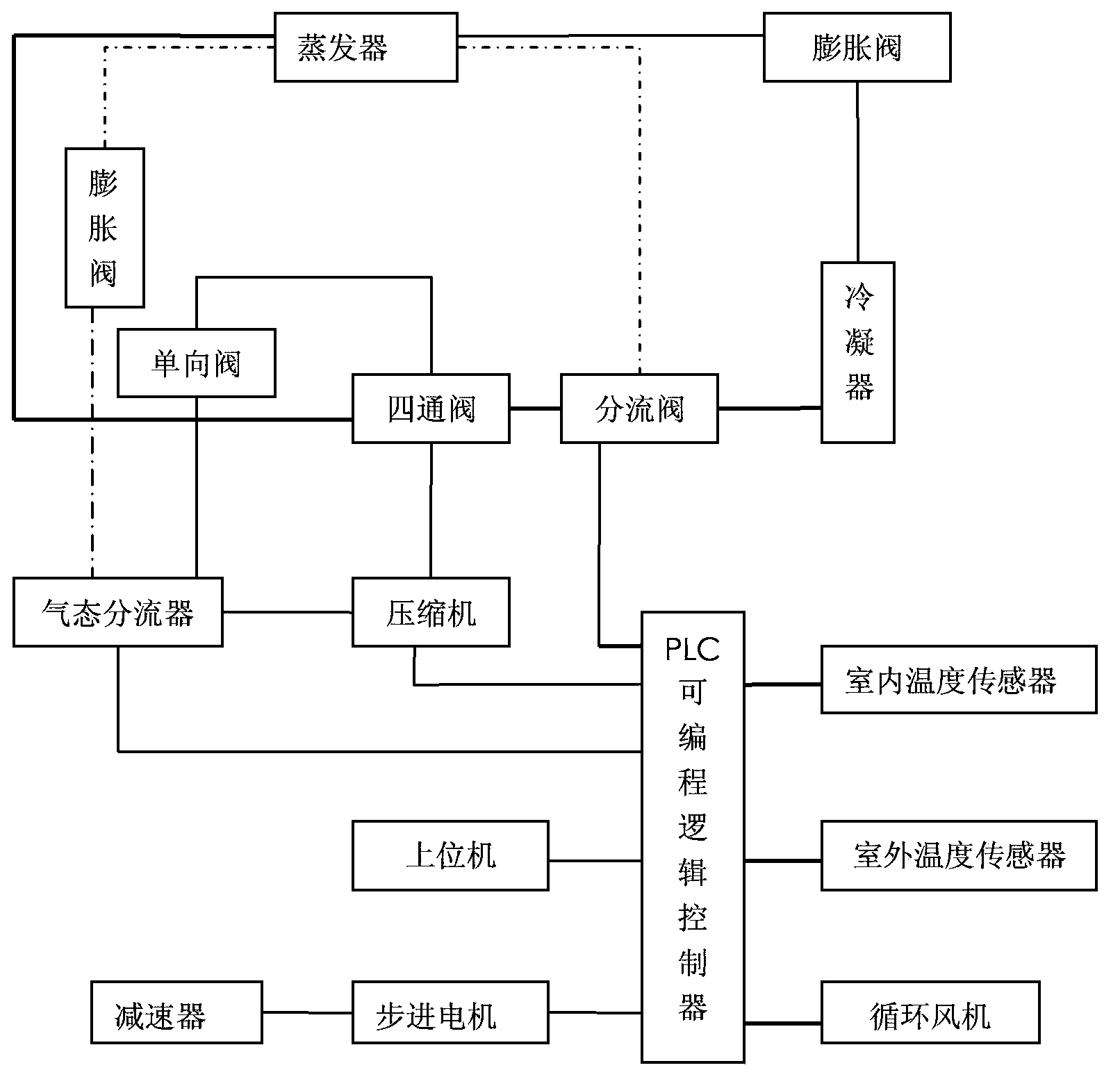
[0012] Referring to the accompanying drawings, the technical solution adopted by the present invention is a control system for an air source heat pump drying production line, which is mainly composed of an air source heat pump unit, a PLC programmable logic controller, a temperature sensor, a host computer, a circulating fan and a stepping motor Composition; the air source heat pump unit includes an evaporator, an expansion valve, a gas-liquid splitter, a compressor, a splitter valve, and a condenser. The PLC programmable logic controller is connected with the indoor temperature sensor, the outdoor temperature sensor, and the The circulating fan, the stepping motor are connected with the upper computer; the stepping motor is connected with the reducer to drive the conveyor belt on the drying production line to run.

[0013] Further, the air source heat pump unit mainly provides heat source for the drying box, the condenser in the air source heat pump unit is installed inside th...


PUM


Abstract

The invention relates to a control system for an air source heat pump drying production line. The control system is mainly composed of an air source heat pump set, a programmable logic controller (PLC), a temperature sensor, an upper computer, a circulating fan and a stepping motor. The air source heat pump set comprises an evaporator, an expansion valve, a gas-liquid flow divider, a compressor, a flow divider valve and a condenser. The PLC is connected with an indoor temperature sensor, an outdoor temperature sensor, the circulating fan, the stepping motor and the upper computer. The stepping motor is connected with a speed reducer and drives a conveying belt on the drying production line to run.

Description

technical field [0001] The invention relates to the field of application of air source heat pumps, in particular to the field of application of air source heat pump systems to production equipment. Background technique [0002] During shoe making, the upper leather is glued to the sole with a liquid adhesive. When producing shoes in large quantities, after the gluing process is completed, the shoes need to be dried rapidly and continuously. At present, shoe-making enterprises often use tunnel furnaces or drying boxes for drying. The heat sources of the above-mentioned tunnel furnaces and drying boxes are often electric heating or Infrared heating consumes a lot of power. [0003] Heat pump technology uses a "pump" method to transmit low-temperature heat source to high-temperature end. It is a heating method that utilizes low temperature. The entire power consumption of heat pump heating is much lower than that of traditional electric heating. When the air source heat pump ...

Claims


Application Information

Patent Timeline
IPC IPC(8): A43D25/20F25B30/06
Inventor 杜贵萍
Owner XIAN JINGJIE ELECTRONICS TECH
Why Eureka
Try Eureka