Special testing device and method for correcting welding track based on machine vision

A technology of machine vision and testing equipment, used in measurement equipment, optical equipment, auxiliary equipment, etc.

Inactive Publication Date: 2014-06-11
SOUTH CHINA UNIV OF TECH
View PDF5 Cites 24 Cited by
  • Summary
  • Abstract
  • Description
  • Claims
  • Application Information

AI Technical Summary

Problems solved by technology

Machine vision technology refers to converting the welded workpiece 2 into an image signal through an industrial camera 1, sending it to the image processing system, and converting it into a digital signal according to pixel distribution, brightness, color and other information; the image system performs various calculations on these signals. Extract the features of the target to determine the offset of the reproduced welding trajectory, so that the welding robot 3 can accurately weld the welding workpiece 2; however, there is no correlation between the accuracy evaluation and verification of the welding trajectory offset determined by machine vision Therefore, it is necessary to develop a special test device, which can evaluate and verify the accuracy of the welding track offset determined by machine vision technology, and analyze the cause of the error, so as to continuously optimize the image processing method in machine vision technology. Enables the realization of accurate detection requirements for welding track offset

Method used


Image

  • Special testing device and method for correcting welding track based on machine vision
  • Special testing device and method for correcting welding track based on machine vision
  • Special testing device and method for correcting welding track based on machine vision

Examples


Embodiment 1

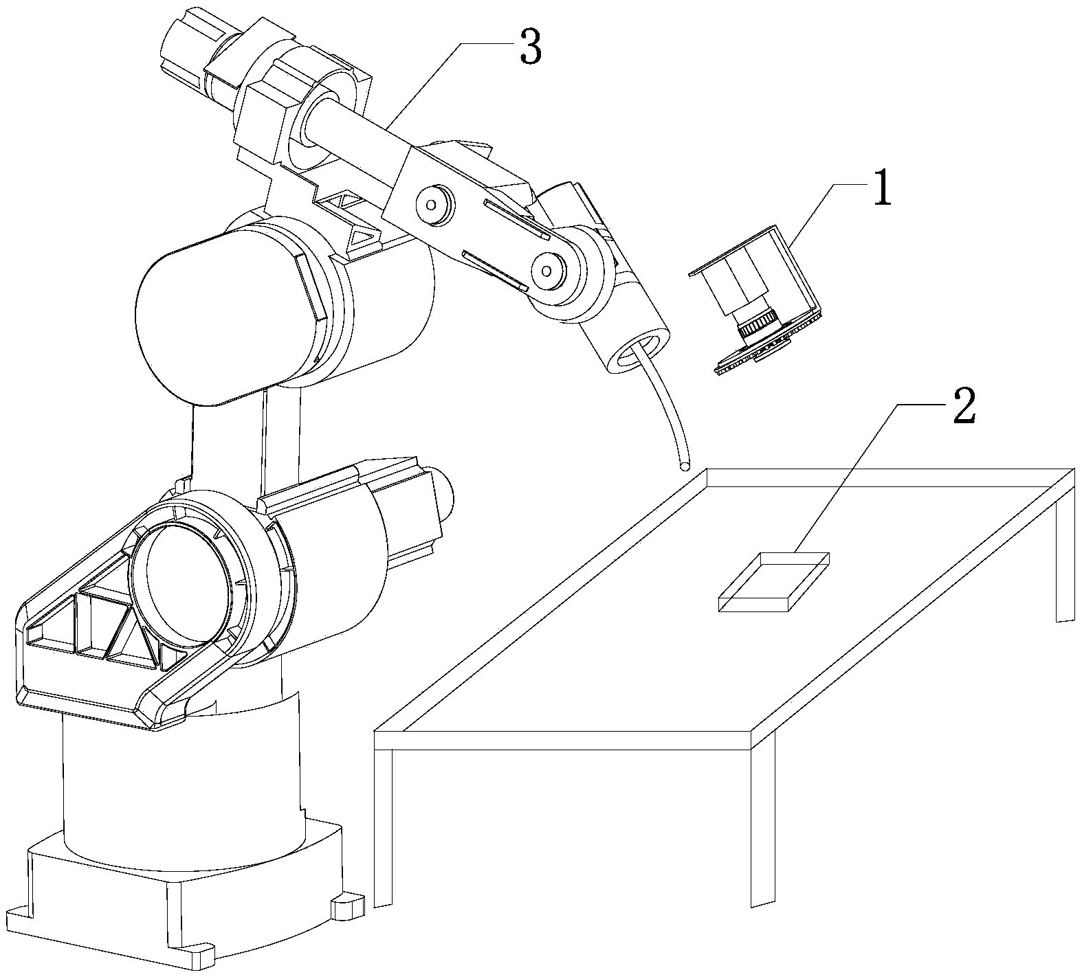
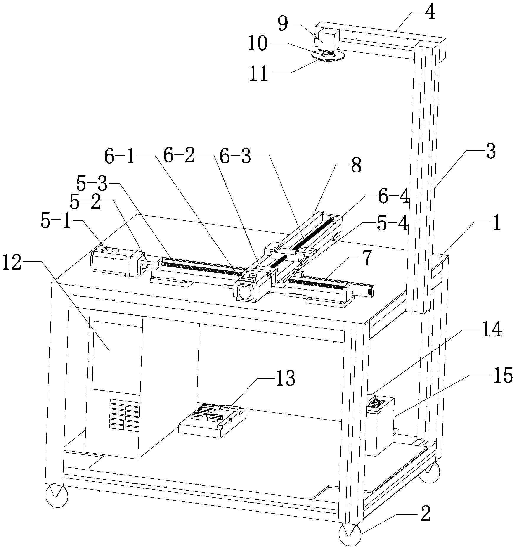
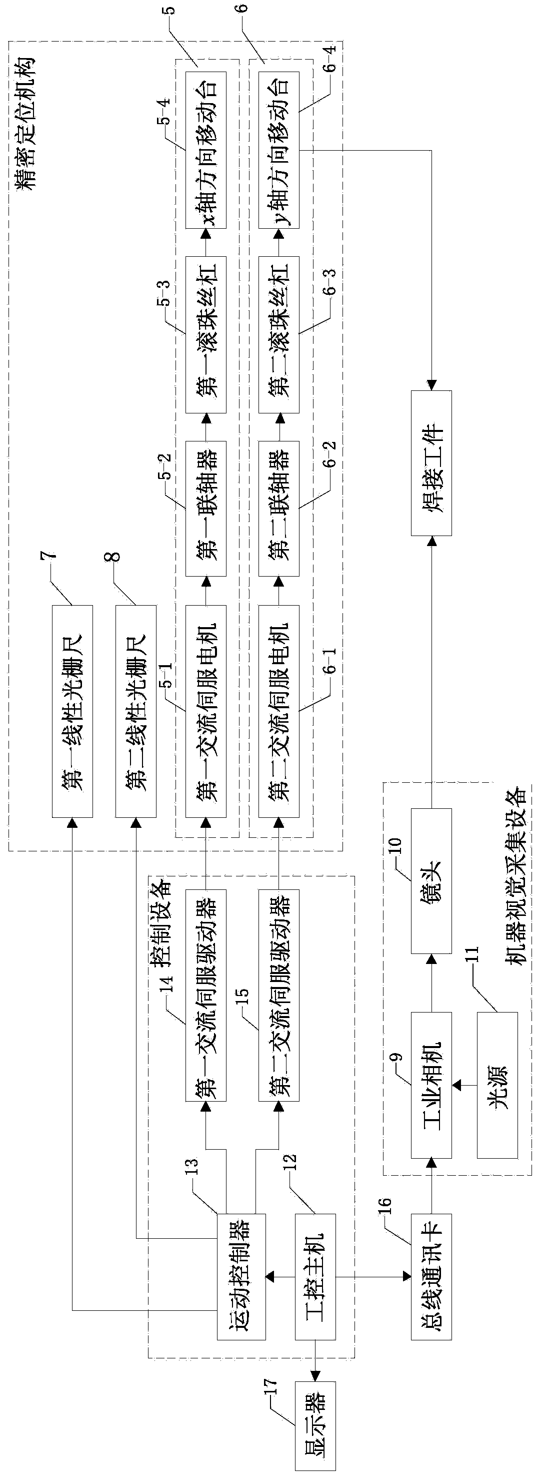
[0042] like figure 2 and image 3 As shown, the special test device for welding trajectory correction based on machine vision in this embodiment includes a workbench 1, a precision positioning mechanism, machine vision acquisition equipment and control equipment. The workbench 1 adopts a frame structure 1, and the frame structure 1 is The frame structure of 1000*800*700mm is made of 40*40 standard aluminum profiles, four wheels 2 are arranged on the bottom to make the workbench 1 move, and a vertical bracket 3 is arranged on one side, on which the vertical bracket 3 A horizontal support 4 is vertically fixed on the top, the precision positioning mechanism is arranged on the top plane of the frame structure 1, the control device is arranged inside the frame structure 1, and the machine vision acquisition device is fixed on the horizontal support 4. The machine vision acquisition device is located above the precise positioning mechanism; the precise positioning mechanism inclu...


PUM


Abstract

The invention discloses a special testing device and method for correcting a welding track based on machine vision. The special testing device comprises a worktable, a precision positioning mechanism, machine vision acquiring equipment and control equipment, wherein the precision positioning mechanism and the machine vison acquiring equipment are respectively connected with the control equipment; the precision positioning mechanism, the machine vision acquiring equipment and the control equipment are arranged on the worktable; the machine vision acquiring equipment is positioned above the precision positioning mechanism; the precision positioning mechanism comprises an x-axis direction driving unit, a y-axis direction driving unit, an x-axis direction position detection unit and a y-axis direction position detection unit. According to the special testing device and method disclosed by the invention, the detection for the offset of the track of a welding workpiece in the x-axis direction and the y-axis direction can be finished based on a machine vison technology, the detection result is estimated and verified, reasons generating errors are analyzed, and an image processing method in the machine vison technology is continuously optimized, and thus the aim of accurately detecting the offset of the welding track is achieved.

Description

technical field [0001] The invention relates to a special testing device for welding trajectory correction, in particular to a special testing device and method for welding trajectory correction based on machine vision, belonging to the technical field of welding trajectory correction. Background technique [0002] Due to the problems of harsh operating environment, heavy labor, and low efficiency in manual welding, robot welding has been gradually applied in many fields such as automobiles, construction machinery, and container production in China. Welding robots usually use the mode of teaching and reproduction. Work, "teaching programming" refers to completing the programming of the program in the following way: manual guidance of the robot end effector (such as: welding gun) to make the robot complete the expected action, "task program" is a set of motion and auxiliary function instructions , to identify robot-specific expected jobs. "Reproduction" means that the robot ...

Claims


Application Information

Patent Timeline
IPC IPC(8): B23K37/047
CPCB23K37/0461G05B19/401G05B2219/45135B23K37/00B25J9/1664B25J13/08G01B11/02
Inventor 李琳李春邹焱飚
Owner SOUTH CHINA UNIV OF TECH
Why Eureka
Try Eureka