Check patentability & draft patents in minutes with Patsnap Eureka AI!

Combined Rotary Drive Unit

A rotary drive, combined technology, applied in metal processing mechanical parts, metal processing, measuring/indicating equipment, etc., can solve the problem of large installation space and volume, achieve less installation space, improve equipment processing accuracy, and reasonable design Effect

Active Publication Date: 2017-07-14
高密宏泰机床制造有限公司
View PDF7 Cites 0 Cited by
  • Summary
  • Abstract
  • Description
  • Claims
  • Application Information

AI Technical Summary

Problems solved by technology

[0005] The technical problem to be solved by the present invention is to provide a combined rotary drive unit to solve the technical problem that the conventional structure of the drive device used in the existing CNC machine tools leads to the installation occupying space and large volume

Method used


Image

  • Combined Rotary Drive Unit
  • Combined Rotary Drive Unit
  • Combined Rotary Drive Unit

Examples


Embodiment 1

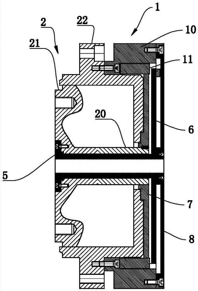
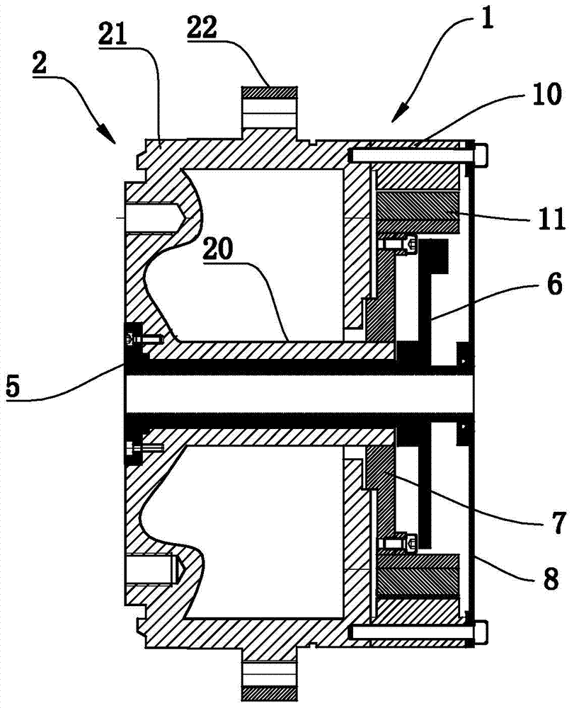
[0020] like figure 1 and figure 2 Commonly shown in , a combined rotary drive unit includes a reducer driven by a direct drive servo motor, the stator of the direct drive servo motor is fixedly connected to the housing of the reducer, and the rotor of the direct drive servo motor passes through a flange 7 Connect with the input terminal of the reducer.

[0021] The output end of the reducer is connected to the detection device used to eliminate the transmission gap. The detection device includes a connecting sleeve 5 that runs through the center hole of the reducer. One end of the connecting sleeve 5 is fixedly connected to the output end of the reducer, and the other end is connected to the encoder. 6 or grating ruler connection, the encoder or grating ruler is connected to the direct drive servo motor through the electronic control unit.

[0022] The reducer is a harmonic reducer 2, the direct drive servo motor is a frameless direct drive servo motor 1, the stator 10 of t...

Embodiment 2

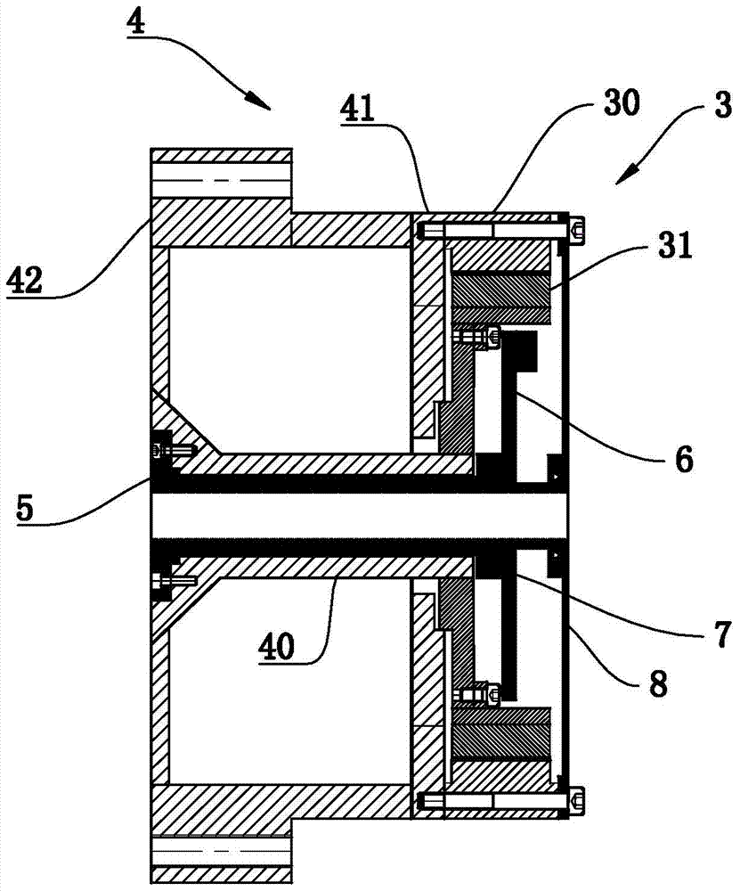
[0028] like image 3 As shown in , the structure of this embodiment is basically the same as that of Embodiment 1, the difference is that the reducer is a harmonic reducer 4, the direct drive servo motor is a frameless direct drive servo motor 3, and the frameless direct drive servo motor 3 The stator 30 of the harmonic reducer 4 is fixedly connected with the steel wheel 41 of the harmonic reducer 4, the rotor 31 of the frameless direct drive servo motor 4 is connected with the wave generator 40 of the harmonic reducer 4 through the flange 7, and the sleeve 5 is connected One end is connected with the output end of the flexible wheel 42 of the harmonic reducer 4 through a fastener, and the other end is connected with the encoder 6 or the grating scale, and the encoder 6 or the grating scale is connected with the frameless direct drive servo motor 3 through the electronic control unit .

[0029] When in use, the drive unit composed of the frameless direct drive servo motor 3 a...


PUM


Abstract

The invention belongs to the technical field of driving units, and particularly relates to a combined type rotation driving unit. The combined type rotation driving unit comprises a speed reducer which is driven by a direct-drive servo motor, wherein a stator of the direct-drive servo motor is fixedly connected to a shell of the speed reducer, and a rotor of the direct-drive servo motor, is connected to the input end of the speed reducer through a flange plate. The combined type rotation driving unit has the beneficial effects of small volume of driving units, small mounting space and high detection precision.

Description

technical field [0001] The invention belongs to the technical field of drive devices, in particular to a combined rotary drive unit. Background technique [0002] CNC machine tool is the abbreviation of numerical control machine tool, which is an automatic machine tool equipped with a program control system. The control system can logically process programs with control codes or other symbolic instructions, decode them, express them in coded numbers, and input them into the numerical control device through the information carrier. After calculation and processing, various control signals are sent by the numerical control device to control the movement of the machine tool, and the parts are automatically processed according to the shape and size required by the drawing. CNC machine tools solve complex, precise, small-batch, and multi-variety parts processing problems. They are flexible and high-efficiency automatic machine tools, so they are widely used. [0003] Due to the...

Claims


Application Information

Patent Timeline
Patent Type & Authority Patents(China)
IPC IPC(8): B23Q5/00B23Q17/24
CPCB23Q5/00B23Q17/007B23Q17/2452
Inventor 杜明乾
Owner 高密宏泰机床制造有限公司
Features
  • R&D
  • Intellectual Property
  • Life Sciences
  • Materials
  • Tech Scout
  • Unparalleled Data Quality
  • Higher Quality Content
  • 60% Fewer Hallucinations
Learn More