Robot system

A robot system and robot technology, applied in the field of robot systems, can solve the problems of not being able to monitor in real time, not being able to record welding construction data for a long time, and not considering multiple welding robots, etc.

Active Publication Date: 2014-06-11
DAIHEN CORP
View PDF10 Cites 8 Cited by
  • Summary
  • Abstract
  • Description
  • Claims
  • Application Information

AI Technical Summary

Problems solved by technology

[0008] (1) The capacity of RAM (Random Access Memory) or connectable memory that can be mounted on the robot controller is actually limited, and it is not possible to record all welding construction data for a long time
[0009] (2) In an arc welding production line composed of multiple robot controllers to store welding construction data in the robot controller, the collected and stored data cannot be collectively managed by each robot controller
[0011] (3) If there is an abnormality in the communication line for some reason, there is no guarantee that the welding construction data can be saved reliably
[0012] (4) Since the welding construction data in 1 welding section is transmitted to the personal computer collectively after the welding is completed, the data during the welding construction cannot be confirmed on the personal computer (that is, real-time monitoring is not possible)
In addition, in the case of welding construction for a large workpiece with a welding time of more than one hour, for example, it takes time to transfer data after welding.
[0013] (5) Multiple welding robots are not considered
[0014] The above-mentioned problems are listed as problems of arc welding robots. However, in industrial robots other than arc welding robots, when a monitoring device and a single or multiple robot control devices are connected via a network, when sending The same problem exists when monitoring values ​​including various information acquired by the robot controller and command information used to control the robot in the robot controller

Method used


Image

  • Robot system
  • Robot system
  • Robot system

Examples


Embodiment Construction

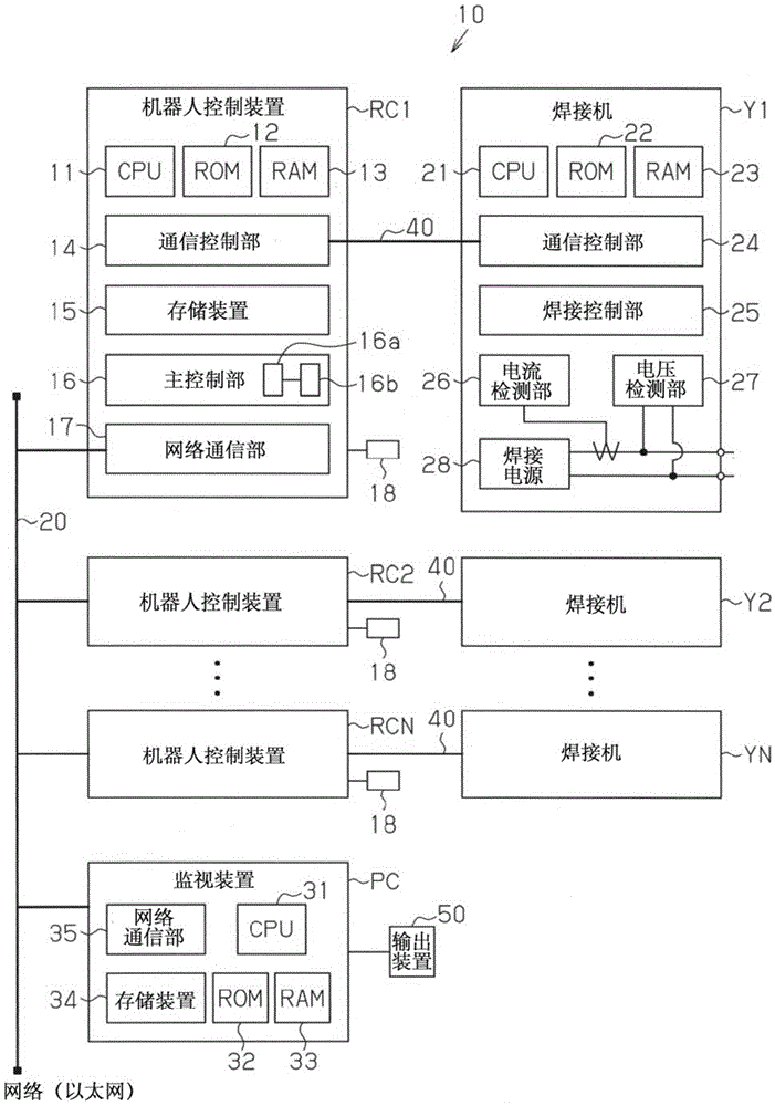
[0035] Below, refer to Figure 1 to Figure 5 An embodiment in which the present invention is embodied as an arc welding robot system will be described.

[0036] like figure 1 As shown, the arc welding robot system 10 includes a plurality of robots (not shown) configured to perform arc welding, robot controllers RC1 , RC2 to RCN, and a monitoring device PC for controlling the robots.

[0037] The robots controlled by the robot controllers RC1 , RC2 to RCN are well-known articulated robots, so the description will be simplified. A manipulator constituting a robot is composed of a base member fixed to an appropriate place such as the ground, a plurality of arms connected to the base member via a plurality of joints, and a drive motor (not shown) that drives each arm. The drive motor includes a rotary encoder (not shown), and can detect the current position of the drive motor. A welding torch for arc welding a workpiece (not shown) as an object to be welded is attached to the d...


PUM


Abstract

The invention provides a robot system. In a production line where a monitoring device and a plurality of robot control devices are connected via the network, when a communication circuit is abnormal, it fails to ensure that welding construction data is reliably stored. Thus, robot control devices (RC1) provided by the invention comprise storing devices (15) and main control parts (16). The storing devices successively store the wielding construction data. The main control parts judge whether idle storing capacity of the storing devices is enough for storing the welding construction data predetermined to be obtained in a to-be-performed welding control procedure. When failing to communicate with a monitoring device (PC), the main control part performs abnormal processing and keeps monitoring associated information stored by the storing devices. When the main control part is capable of communicating with the monitoring device, or becomes to be capable of carrying out communication from a communication failure, the welding construction data of the storing devices are sent to the monitoring device. The welding construction data can be reliably stored, so traceability of the whole production line can be ensured.

Description

technical field [0001] The present invention relates to robotic systems. Background technique [0002] In the labor-saving or unmanned arc welding production line in recent years, all welding construction data (command value and actual value) are reliably recorded for each welding part of each welding workpiece, so that they can be traced afterwards. In quality management, the so-called The assurance of traceability becomes very important. Patent Document 1 and Patent Document 2 are known as such techniques. [0003] Patent Document 1 proposes a technique of collecting and displaying waveform data when an arc welding robot alone performs a welding operation without using external equipment. [0004] In Patent Document 2, the welding current during arc welding is monitored by a robot controller. For example, when the welding operation of 1 welding section is completed, the monitored current value is saved in a file and transmitted to the connected personal computer via Eth...

Claims


Application Information

Patent Timeline
Patent Type & Authority Applications(China)
IPC IPC(8): B25J9/22B25J9/16B23K9/32B23K9/095
CPCY02P90/02
Inventor 山本真央广田周吾
Owner DAIHEN CORP
Why Eureka
Try Eureka