Low-cost integrated steam turbine lubricating oil system for power station auxiliary equipment

A steam turbine, low-cost technology, applied in the direction of machines/engines, mechanical equipment, engine components, etc., can solve problems such as the time that the equipment is put into use, the connection strength is not high, and the installation workload is large, so as to reduce the on-site debugging work, The effect of reducing installation workload and ensuring equipment availability

Inactive Publication Date: 2014-06-11
CHANGSHU HIGH PRESSURE VESSEL MFG
View PDF10 Cites 3 Cited by
  • Summary
  • Abstract
  • Description
  • Claims
  • Application Information

AI Technical Summary

Problems solved by technology

[0003] like figure 1 As shown, at present, the main equipment of the lubricating oil system of the steam turbine includes a cylindrical horizontal oil tank 1, an oil fume purification and discharge device 2, an AC oil pump 3, a DC oil pump 4, a filter 5 and an oil cooler 6. The above-mentioned components pass through the pipeline Connection and installation, the connection strength between each part is not high, if it is installed and debugged and then transported as a whole, it is very likely to cause damage to the system during transportation, so it can only be shipped to the power plant in bulk with the internal connection pipes and valves, and then in the power plant On-site assembly and debugging
However, due to the many and scattered components of the system, the on-site installation workload is large, time-consuming and labor-intensive, and the commissioning is carried out on-site, so it is difficult to ensure the availability of the equipment. If any component of the equipment is unqualified, it needs to be sent back for repair , will greatly affect the time when the equipment is put into use, and the efficiency is extremely low

Method used


Image

  • Low-cost integrated steam turbine lubricating oil system for power station auxiliary equipment
  • Low-cost integrated steam turbine lubricating oil system for power station auxiliary equipment

Examples


Embodiment Construction

[0019] Below in conjunction with the embodiment shown in the accompanying drawings, the present invention is described in detail as follows:

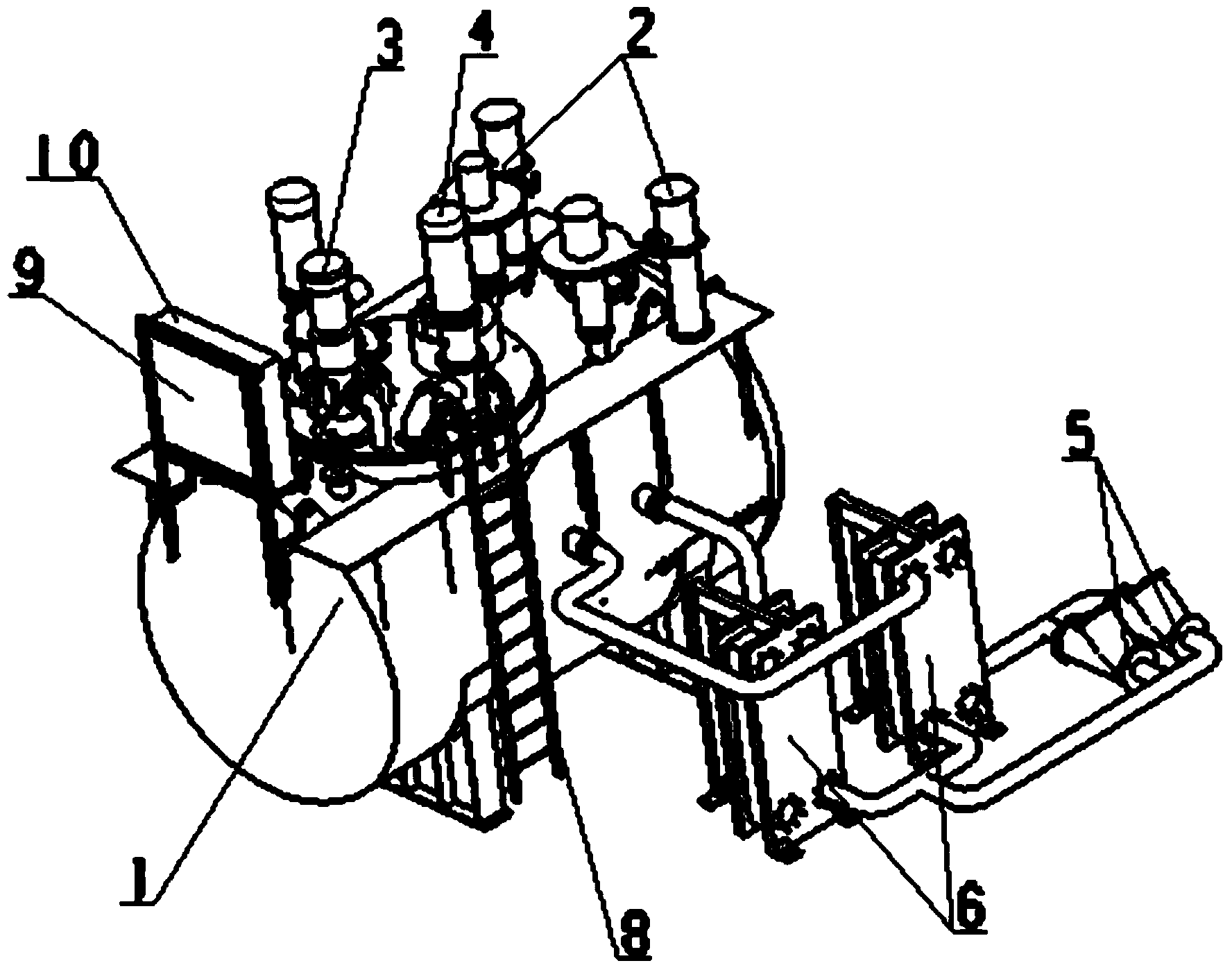
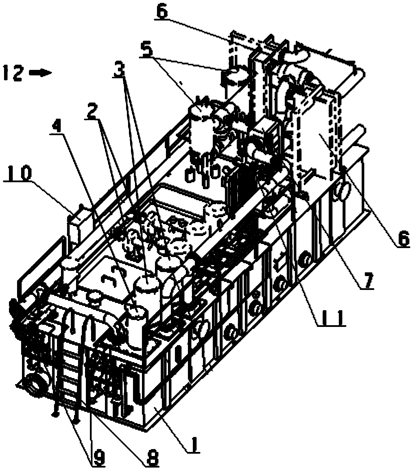
[0020] like figure 2 As shown, the steam turbine lubricating oil system includes an oil tank 1 , a bearing oil supply part 12 , a jacking shaft oil supply part 11 and an oil fume purification and discharge device 2 .

[0021] The bearing oil supply part 12 includes at least one AC lubricating oil pump 3, a DC emergency oil pump 4, a filter 5, an oil cooler 6, and a temperature control valve 7. In this embodiment, there are two AC lubricating oil pumps 3, and one is in a normal working state , and the other is in the standby state. When one AC lubricating oil pump 3 fails, the AC lubricating oil pump 3 in the standby state starts. When both AC lubricating oil pumps 3 fail, the DC emergency oil pump 4 starts to fully ensure the system. normal operation. The temperature control valve 7 is a three-way temperature control valve, the filte...


PUM


Abstract

The invention relates to a low-cost integrated steam turbine lubricating oil system for power station auxiliary equipment, which comprises an oil tank, a bearing oil supply part, a jacking shaft oil supply part and an oily fume purification discharge device. According to the invention, the bearing oil supply part, the jacking shaft oil supply part and the oily fume purification discharge device are all arranged on the upper end face of the oil tank; the low-cost integrated steam turbine lubricating oil system for the power station auxiliary equipment leaves a factory after being assembled; field installation workload is reduced; each part of the low-cost integrated steam turbine lubricating oil system is arranged in a centralizing manner; the low-cost integrated steam turbine lubricating oil system is convenient to maintain; before leaving the factory, the system is subjected to performance testing, so that field debugging work is reduced and equipment availability is ensured; a temperature control valve is added, so that the oil supply temperature of lubricant oil is stabilized.

Description

technical field [0001] The invention relates to the field of steam turbines, in particular to a steam turbine lubricating oil system. [0002] Background technique [0003] like figure 1 As shown, at present, the main equipment of the lubricating oil system of the steam turbine includes a cylindrical horizontal oil tank 1, an oil fume purification and discharge device 2, an AC oil pump 3, a DC oil pump 4, a filter 5 and an oil cooler 6. The above-mentioned components pass through the pipeline Connection and installation, the connection strength between each part is not high, if it is installed and debugged and then transported as a whole, it is very likely to cause damage to the system during transportation, so it can only be shipped to the power plant in bulk with the internal connection pipes and valves, and then in the power plant On-site assembly and debugging. However, due to the many and scattered components of the system, the on-site installation workload is large,...

Claims


Application Information

Patent Timeline
Patent Type & Authority Applications(China)
IPC IPC(8): F01D25/20
Inventor 时仁元陶明华阚宏杰
Owner CHANGSHU HIGH PRESSURE VESSEL MFG
Why Eureka
Try Eureka