Multifunctional ignition device

An ignition device and multi-functional technology, applied in the direction of combustion ignition, lighting and heating equipment, combustion methods, etc., can solve the problems of unable to form a stable fire source, unable to form a stable fire source, large air fluctuations, etc., to facilitate online debugging and The effect of setting

Active Publication Date: 2014-03-26
斯文杰
View PDF1 Cites 2 Cited by
  • Summary
  • Abstract
  • Description
  • Claims
  • Application Information

AI Technical Summary

Problems solved by technology

[0006] 2. The composition of gas sources in petrochemical plants varies greatly, and the applicability of a single gas source is poor;
[0007] 3. The outlet 16 of the first fire source pipeline described in this patent is connected to the second fire source 30. Since the first fire source deflagrates, the speed of sound in the pipeline has exceeded 1 / s, and the speed of the second gas source is only Tens of meters per second, unable to form a stable fire source;
[0008] 4. The three elements of ignition: combustibles, air (oxygen), and ignition source. After 16 is connected with the second fire source 30, the concentration of combustible gas in the pipeline is too high, and there is no air (oxygen) in the pipeline to burn. form a stable fire source;
[0009] 5. During the operation of the petrochemical plant, the air fluctuates greatly, and there is no pressure stabilizing device, so the mixing ratio of air and fuel gas cannot be guaranteed, and it is difficult to mix it to reach the deflagration range during ignition;
[0010] 6. After the air and fuel gas are mixed at 10 in the figure, they enter the ignition device through the pipeline 11, the flow-restricting orifice 12, and the check valve 13. Because they are mixed before the flow-restricting orifice, the fuel gas is easily poured in when the air pressure is low. Air ducts, leaving a great safety hazard;
[0011] 7. The patent uses a flowmeter, but the flowmeter is expensive and easy to damage;
[0012] 8. Flow control is adopted, the flow meter is only a measuring instrument, there is no regulating valve in the process flow, and the flow control of air and fuel gas cannot be performed

Method used


Image

  • Multifunctional ignition device

Examples


Embodiment Construction

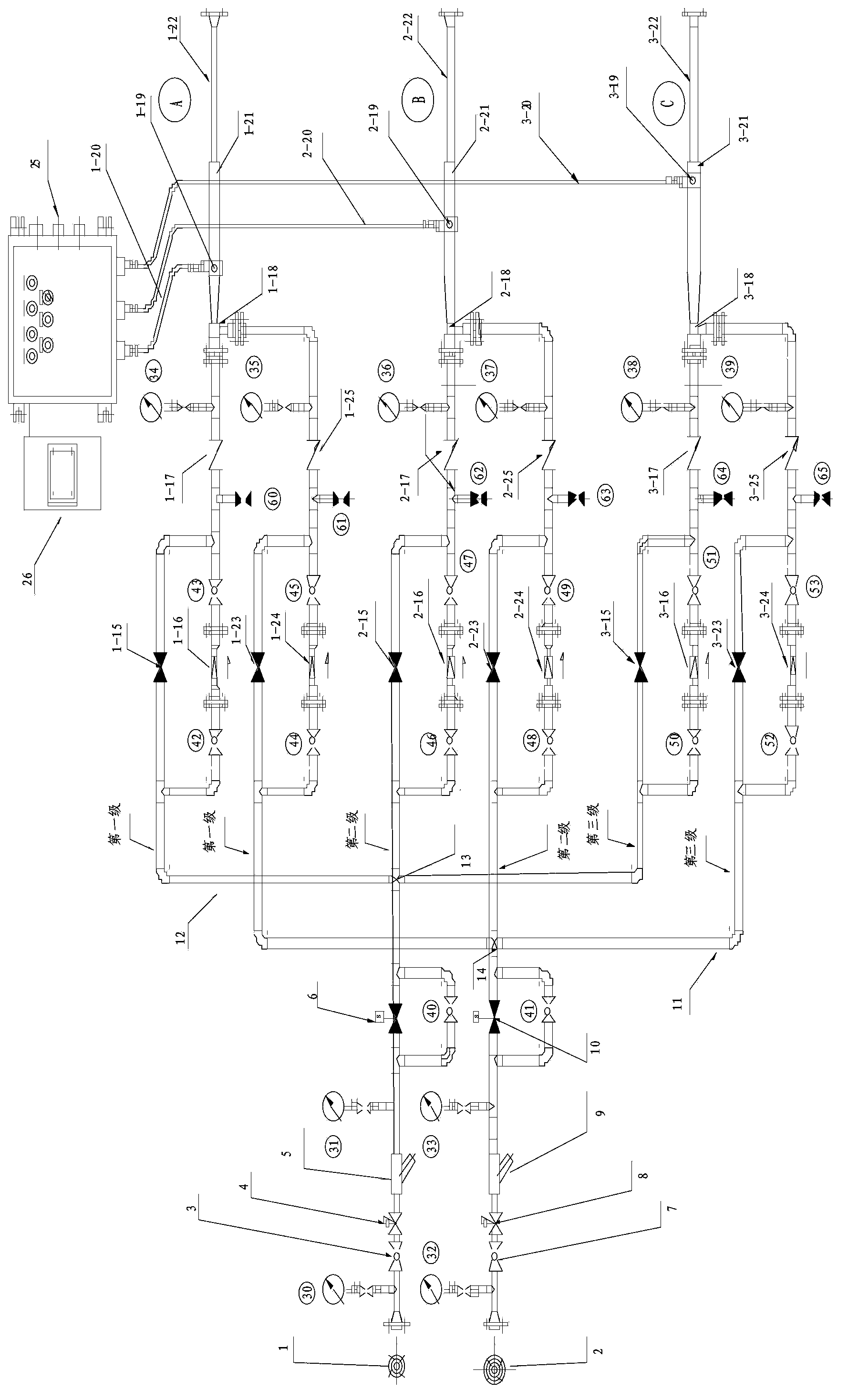
[0042] Below in conjunction with accompanying drawing, the present invention is described in further detail:

[0043] Such as figure 1 As shown, a multifunctional ignition device, figure 1 An example is given, wherein the compressed air supply device and the fuel gas supply device respectively have three-stage pipelines, which are respectively the first stage, the second stage and the third stage, wherein the compressed air supply device passes through The air four-way pipe fitting 13 separates the three-stage air pipeline 12, and the fuel gas supply device divides the three-stage gas pipeline 11 through the gas four-way pipe fitting 14. In actual use, according to actual needs, the compressed air supply device and the fuel gas supply device Each can be more or less than three levels. figure 1 Among them, the compressed air and fuel gas pipelines are connected with the air flange 1 and the gas flange 2 of the multi-functional ignition device, respectively pass through the ma...


PUM


Abstract

The invention provides a multifunctional ignition device and belongs to the field of ignition devices. The multifunctional ignition device comprises a compressed air supply device, a fuel gas supply device, the deflagration chamber, a flame tube and a full-automatic ignition control box; the compressed air supply device comprises at least one primary air main pipe; the fuel gas supply device comprises at least one primary fuel gas main pipe; the air out of the compressed air supply device and the fuel gas out of the fuel gas supply device are mixed to form the combustible mixed gas which is connected with the flame tube in the deflagration chamber; the full-automatic ignition control box is used for performing automatic ignition and accordingly the combustible mixed gas is ignited automatically or manually. According to the multifunctional ignition device, the automatic ignition control in the control chamber or other distant places and the on-site direct operation of automatic ignition and manual ignition at the position of the ignition device can be achieved simultaneously.

Description

technical field [0001] The invention belongs to the field of ignition devices, and in particular relates to a multifunctional ignition device. Background technique [0002] The success rate of ground deflagration ignition is only 30% to 50% when the existing torch high-altitude ignition device is damaged, and the adjustment time is long, and it is difficult to control the adjustment ratio (the mixing ratio of fuel gas and air), and it cannot Realize remote, local automatic and manual ignition functions; [0003] The existing ignition adjustment ratio has a low probability of success rate, and the mixed deflagration ratio of air and gas is small (that is, the mixture of air and gas is not easy to reach the deflagration ratio). When any factor such as the fuel gas component pressure and air pressure changes, no matter whether it is on-site or remote, the ignition cannot be successful on the spot, and it needs to be adjusted repeatedly before it can be used. Moreover, if the ...

Claims


Application Information

Patent Timeline
Patent Type & Authority Applications(China)
IPC IPC(8): F23Q13/04F23Q21/00
Inventor 斯文杰
Owner 斯文杰
Why Eureka
Try Eureka