Imaging lens capable of eliminating stray light

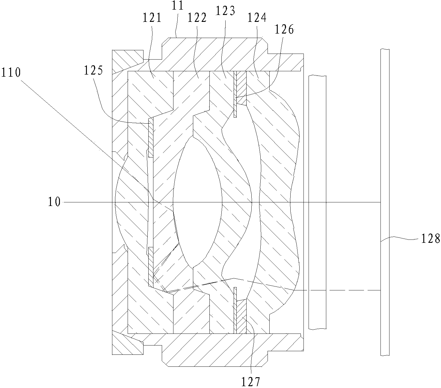
一种成像镜头、光线的技术,应用在成像镜头领域,能够解决遮光组件125、126易变形贴附、遮光作用与成像质量不理想、无法有效排除杂散光线等问题,达到良好组装精确度、减少厚度、容易制作的效果

Inactive Publication Date: 2014-06-11
GENIUS ELECTRONICS OPTICAL XIAMEN
View PDF9 Cites 36 Cited by
  • Summary
  • Abstract
  • Description
  • Claims
  • Application Information

AI Technical Summary

Problems solved by technology

[0003] However, the existing shading components 125 and 126 still cannot effectively eliminate the stray light incident at a large angle, such as figure 1 A stray ray 110 shown in , after being reflected and refracted between the lens barrel 11 and the lenses 121, 122, 123, 124, will still be imaged on an imaging surface 128, causing the stray ray 110 to still affect the image quality , therefore, it is necessary to provide an imaging lens that can effectively eliminate stray light to obtain better imaging quality
[0004] In addition, because the thickness of the shading components 125, 126 is extremely thin, if the contact surfaces between the lenses 121, 122, 123, 124 and the shading components 125, 126 are uneven due to manufacturing tolerances, they will A gap is generated, which makes the shading components 125, 126 easily deformed and difficult to be smoothly attached to the plurality of lenses 121, 122, 123, 124, thereby affecting the assembly accuracy of the imaging lens, resulting in unsatisfactory shading effect and imaging quality. Therefore, in addition to the high difficulty in manufacturing parts and the large number of assembled components, it is difficult to maintain a good assembly accuracy in this imaging lens, and there is also the problem that the imaging quality is easily affected by poor assembly.

Method used


Image

  • Imaging lens capable of eliminating stray light
  • Imaging lens capable of eliminating stray light
  • Imaging lens capable of eliminating stray light

Examples


Embodiment Construction

[0054] The aforementioned and other technical contents, features and effects of the present invention will be clearly presented in the following detailed descriptions of several preferred embodiments with reference to the accompanying drawings.

[0055] Before the present invention is described in detail, it should be noted that in the following description, similar components are denoted by the same numerals. And in order to more clearly present the structure of the cutaway part of the component, the outline lines of the non-cutaway parts are omitted in each drawing.

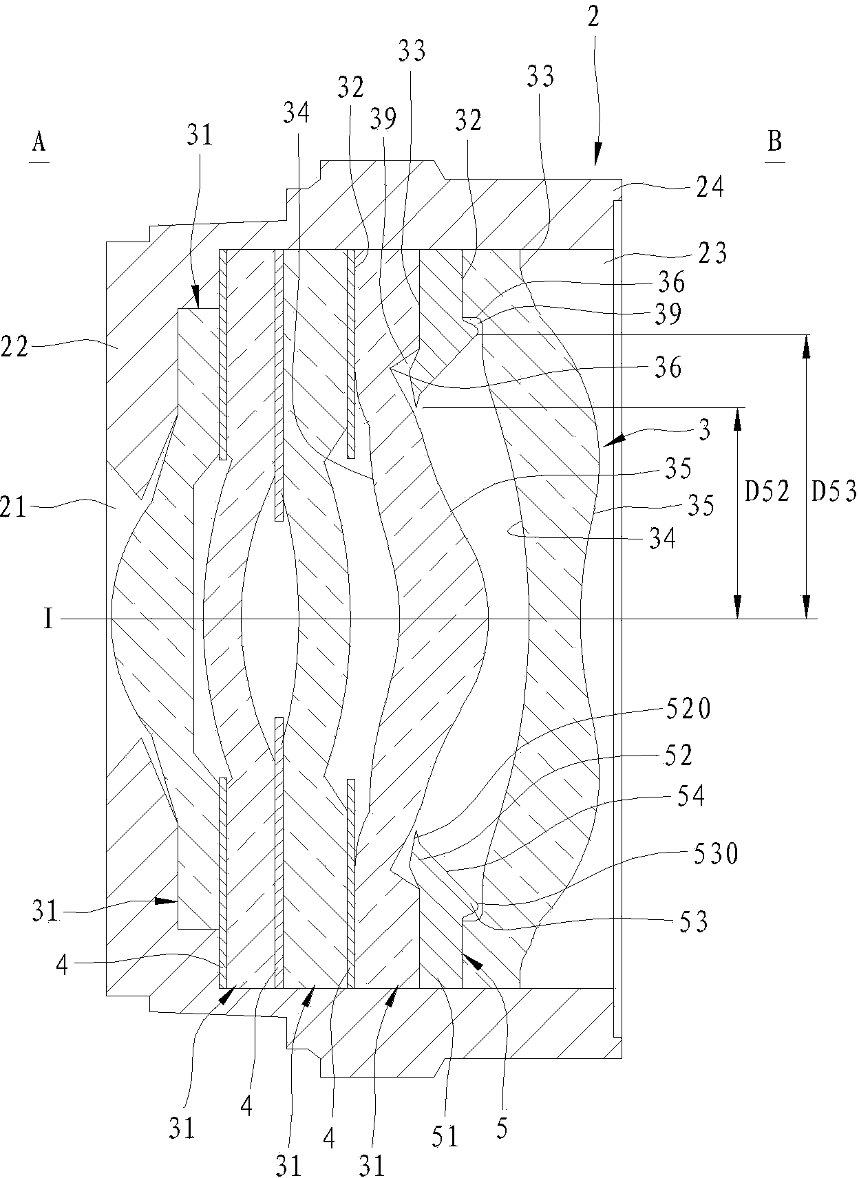
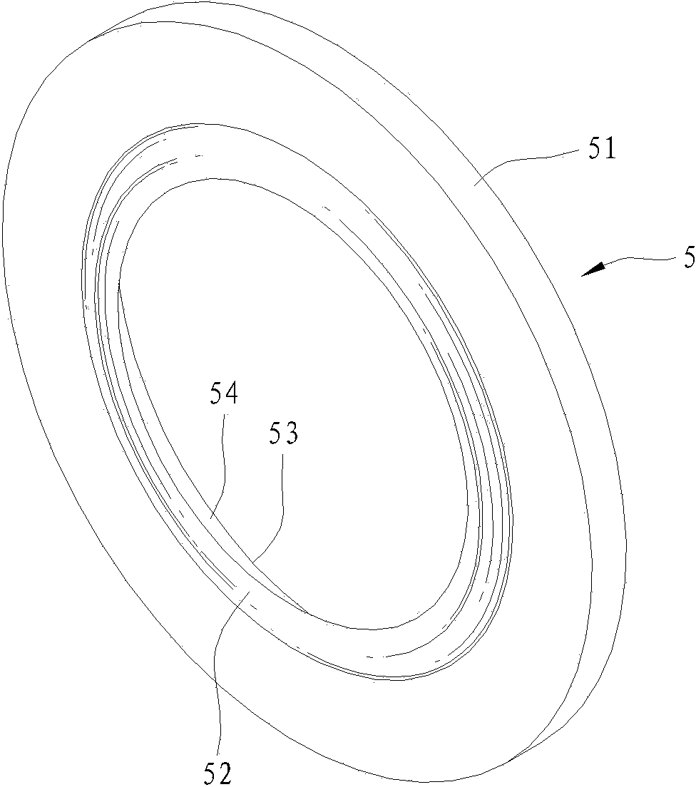
[0056] refer to figure 2 , image 3 and Figure 4 , a first preferred embodiment of the imaging lens capable of eliminating stray light in the present invention includes a lens barrel 2 , an imaging unit 3 , several shading sheets 4 , and a shading assembly 5 .

[0057] The lens barrel 2 includes a base wall 22 that defines a light entrance hole 21 around an optical axis I and is adjacent to the object side...


PUM


Abstract

The invention relates to an optical imaging lens capable of being applied to a lens module for image shooting and picture recording. The imaging lens capable of eliminating stray light comprises a lens cone, an imaging unit arranged in the lens cone and a shading assembly arranged in the imaging unit. The shading assembly comprises a fixing portion arranged on the imaging unit in a clamping mode, an object side protruding portion and an image side protruding portion, the object side protruding portion protrudes from the inner periphery, close to an object side, of the fixing portion, extends inwards in a tilted mode and ends at a tail end edge, and the image side protruding portion protrudes from the inner periphery, close to an image side, of the fixing portion, extends inwards in a tilted mode and ends at a tail end edge. The fixing portion of the shading assembly enables the shading assembly to be located and assembled easily, so that good assembly accuracy can be maintained; the object side protruding portion and the image side protruding portion can effectively eliminate the stray light so as to reduce unnecessary influences of the stray light during imaging. The imaging lens has higher imaging quality.

Description

technical field [0001] The invention relates to an optical imaging lens applicable to a lens module for shooting images and video recordings, in particular to an imaging lens capable of eliminating stray light. Background technique [0002] refer to figure 1 , an existing imaging lens has a lens barrel 11, a plurality of lenses 121, 122, 123, 124 installed inside the lens barrel 11 along the optical axis 10, and two are respectively arranged between the lenses 121, 122 and the lens 123, The shading components 125 , 126 between 124 , and a gasket 127 sandwiched between the shading component 126 and the lens 124 . The shading components 125, 126 are used to eliminate stray light so as not to affect the image quality. The washer 127 can reduce the thickness of the assembly part of the lens 124 to facilitate the manufacture of the lens 124 . [0003] However, the existing shading components 125 and 126 still cannot effectively eliminate the stray light incident at a large ang...

Claims


Application Information

Patent Timeline
Patent Type & Authority Applications(China)
IPC IPC(8): G02B7/02G02B7/00
CPCG02B7/02G02B27/0018G02B7/022G02B13/004G02B13/0045G02B13/0035
Inventor 卓宏章邓一满薛玲慧
Owner GENIUS ELECTRONICS OPTICAL XIAMEN
Why Eureka
Try Eureka