Homogeneous three-phase reactor for jet aeration

A jet aeration and reactor technology, applied in chemical instruments and methods, treatment with moving solid particles, chemical/physical processes, etc., can solve problems such as low reaction efficiency, difficulty in gas, and sufficient and uniform mixing of liquid and solid three-phase , to achieve high reaction efficiency, ensure utilization efficiency, and fully react

Active Publication Date: 2014-06-18
BEIJING HUASHI UNITED ENERGY TECH & DEV
View PDF5 Cites 17 Cited by
  • Summary
  • Abstract
  • Description
  • Claims
  • Application Information

AI Technical Summary

Problems solved by technology

[0005] The technical problem to be solved by the present invention is that it is difficult for the three-phase slurry bed reactor in the prior art to fully and uniformly mix the three phases of gas, liquid and solid, and the reaction efficiency is low. Jet aeration three-phase homogeneous reactor with uniform mixing of three phases and high reaction efficiency

Method used


Image

  • Homogeneous three-phase reactor for jet aeration
  • Homogeneous three-phase reactor for jet aeration
  • Homogeneous three-phase reactor for jet aeration

Examples


Embodiment 1

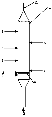
[0038] This embodiment provides a jet aeration three-phase homogeneous reactor, its structure is as follows figure 1 shown, including:

[0039] The reactor shell 1 is connected to the bottom of the reactor shell with a slurry inlet channel 11, and connected to the top of the reactor shell with a discharge channel 12;

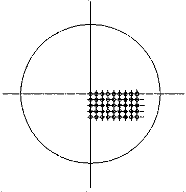
[0040] The jet aeration three-phase homogeneous plate 2, the jet aeration three-phase homogeneous plate is horizontally arranged in the reactor shell and is located at the bottom of the reactor shell, such as image 3 and Figure 4 As shown, micropores 21 are evenly arranged on the jet aeration three-phase homogeneous plate 2, and the micropores are set through the jet aeration three-phase homogeneous plate; as an optional embodiment, the jet The porosity of the micropores on the aerated three-phase homogeneous plate is 0.0001-0.1, and the distance between two adjacent micropores is 100-10000 microns. As a preferred embodiment, the porosity described in this e...

Embodiment 2

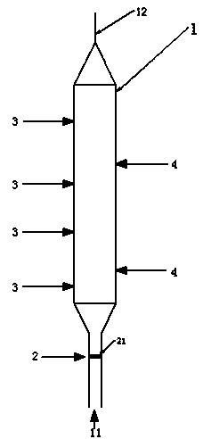
[0047] The jet aeration three-phase homogeneous reactor described in this embodiment has the following structure: figure 2 shown, including:

[0048] The reactor shell 1 is connected to the bottom of the reactor shell with a slurry inlet channel 11, and connected to the top of the reactor shell with a discharge channel 12;

[0049] The jet aeration three-phase homogeneous plate 2, the jet aeration three-phase homogeneous plate is arranged in the described slurry inlet channel, and is parallel to the cross section of the described slurry inlet channel 11; the jet aeration three-phase homogeneous plate Micropores 21 are evenly arranged on the mass plate 2, and the micropores are set through the jet aeration three-phase homogeneous plate; as an optional embodiment, the pores of the micropores on the jet aeration three-phase homogeneous plate The ratio is 0.0001-0.1, and the distance between every two adjacent micropores is 100-10000 microns. Preferably, the porosity described i...


PUM

PropertyMeasurementUnit
specific surface areaaaaaaaaaaa
pore sizeaaaaaaaaaa
specific surface areaaaaaaaaaaa

Abstract

The invention relates to a homogeneous three-phase reactor for jet aeration. A three-phase homogenizing plate for jet aeration is arranged at the bottom of a reactor shell or inside a slurry inlet channel; a micro-pore penetrating through the three-phase homogenizing plate for jet aeration is formed in the three-phase homogenizing plate for jet aeration, so that a three-phase mixture of an oil product, hydrogen and a catalyst flows through the micro-pore, and air bubbles of the gas and liquid drops of the liquid become fine and even. Thus, diffusion and full contact of gas, liquid and solid three-phase substances are facilitated by fine and homogenized air bubbles and liquid drops. The homogeneous three-phase reactor for jet aeration disclosed by the invention can achieve full and even mixing of the oil product, the hydrogen and the catalyst, thus a full touch opportunity is created for reaction of the oil product and the hydrogen on the surface of the catalyst, so that reaction is complete and the reaction efficiency is high.

Description

technical field [0001] The invention relates to a jet aeration three-phase homogeneous reactor, which belongs to the technical field of hydrogenation catalysis. Background technique [0002] Many high-temperature hydrogenation chemical reactions in petroleum industry production need to be synthesized by heterogeneous catalytic reactions. The existing heterogeneous catalytic reactors can be divided into two categories according to the state of the solid catalyst: reactors in a static state and reactors in a flowing state. Among them, the reactor in which the catalyst is in a static state includes a fixed bed reactor, and the reactor in which the catalyst is in a flowing state includes a fluidized bed reactor, a moving bed reactor, and a slurry bed reactor. [0003] At present, most of the slurry bed reactors used in the field of high pressure hydrogenation of heavy oil are slurry bed reactors, and the slurry bed reactors that can be used in the field of high pressure hydroge...

Claims


Application Information

Patent Timeline
Patent Type & Authority Applications(China)
IPC IPC(8): B01J8/22C10G49/12
Inventor 李林郭立新林科路阳王培姜玖辉
Owner BEIJING HUASHI UNITED ENERGY TECH & DEV
Why Eureka
Try Eureka