
Ultraviolet sterilization device used for water treatment and coated with photocatalytic materials

A technology of a sterilization device and a catalytic material, which is applied in the field of water treatment, can solve the problems of poor sterilization and water treatment capacity, high energy consumption cost of consumables, and unsatisfactory sterilization efficiency, so as to save energy consumption cost of consumables, improve capacity, and improve sterilization. effect of potency

Inactive Publication Date: 2014-06-18
北京国中科创环境科技有限责任公司
View PDF6 Cites 13 Cited by
  • Summary
  • Abstract
  • Description
  • Claims
  • Application Information

AI Technical Summary

Problems solved by technology

Now the conventional sterilization method one is ultraviolet irradiation, the second method is to rely on chemical agents, the conventional sterilization device is to place an ultraviolet lamp tube in a closed container, or use a dosing pump to add a chemical agent solution to the main water outlet pipe, the result is either The sterilization efficiency is not ideal, or the energy consumption cost of consumables is high, that is, the ability to sterilize and treat water under the same conditions is not strong

Method used


Image

  • Ultraviolet sterilization device used for water treatment and coated with photocatalytic materials
  • Ultraviolet sterilization device used for water treatment and coated with photocatalytic materials
  • Ultraviolet sterilization device used for water treatment and coated with photocatalytic materials

Examples


Embodiment 1

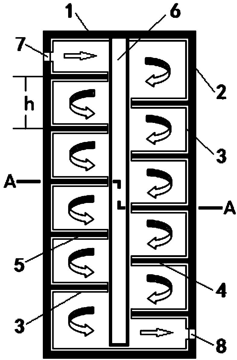
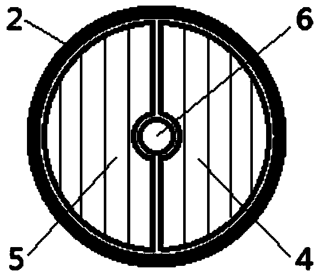
[0028] A closed cylinder is composed of a cylinder wall and a cylinder cover. Two sets of parallel and misaligned semicircular baffles are fixed on the cylinder wall. The baffles in each group are also parallel to each other. The left semicircular baffle The included angle α with the central axis and the included angle β between the right semicircular baffle and the central axis are both 90 degrees, the distance h between two adjacent baffles in each set of baffles is 50 mm, and the inner surface of the cylinder And the surface of the baffle is coated with nano-TiO 2 1. An ultraviolet lamp tube is placed on the central axis of the cylinder, and a water inlet and a water outlet are opened at both ends of the cylinder wall.

[0029] Raw water flows in from the water inlet at one end of the cylinder, and flows through the dislocation gap between two sets of parallel semicircular baffles. The photocatalytic material is sterilized on its surface after being irradiated by ultraviole...

Embodiment 2

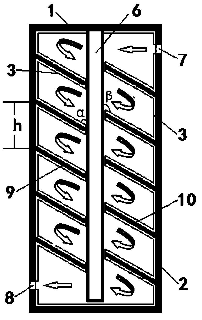
[0031] A closed cylinder is composed of a cylinder wall and a cylinder cover. Two sets of parallel and misplaced semi-elliptical baffles are fixed on the cylinder wall. The baffles in each group are also parallel to each other. The left semi-elliptical baffle The included angle α with the central axis is 60 degrees, the included angle β between the right semi-elliptical baffle and the central axis is 120 degrees, the interval h between two adjacent baffles in each group is 100 mm, and the inner surface of the cylinder And the surface of the baffle is fixedly coated with composite oxide TiO 2 -SnO 2 A reflective gasket, an ultraviolet lamp tube is placed on the central axis of the cylinder, and a water inlet and a water outlet are opened at both ends of the cylinder wall.

[0032] Raw water flows in from the water inlet at one end of the cylinder, and flows through the dislocation gap between two sets of parallel semi-elliptical baffles. The photocatalytic material is sterilized...

Embodiment 3

[0034] A closed cylinder is composed of a cylinder wall and a cylinder cover. Two sets of non-parallel and misplaced semi-elliptical baffles are fixed on the cylinder wall. The baffles in each group are parallel to each other, and the left semi-elliptical baffle The included angle α with the central axis is 60 degrees, the included angle β between the right semi-elliptical baffle and the central axis is also 60 degrees, and the interval h between two adjacent baffles in each group is 100 mm. The surface and the baffle surface are fixedly coated with composite oxide ZnO-SnO 2 A reflective gasket, an ultraviolet lamp tube is placed on the central axis of the cylinder, and a water inlet and a water outlet are opened at both ends of the cylinder wall.

[0035] Raw water flows in from the water inlet at one end of the cylinder, and flows through the dislocation gap between two sets of non-parallel semi-elliptical baffles. The photocatalytic material is sterilized on its surface aft...


PUM


Abstract

The invention relates to an ultraviolet sterilization device used for water treatment and coated with photocatalytic materials, belonging to the technical field of water treatment. The ultraviolet sterilization device comprises a cylinder and an ultraviolet lamp tube, wherein a water inlet is formed in one side of the upper part of the cylinder, a water outlet is formed in the other opposite side of the lower part of the cylinder, a cylinder cover is arranged on the cylinder, the ultraviolet lamp tube is arranged at the center of the cylinder, the upper end of the ultraviolet lamp tube is fixed on the cylinder cover, a left baffle and a right baffle are respectively a left semicircular baffle and a right semicircular baffle, the arc-shaped sections of a plurality of left semicircular baffles are evenly distributed and fixed on the left-side cylinder wall along with the axial direction of the cylinder, the arc-shaped sections of a plurality of right semicircular baffles are evenly distributed and fixed on the right-side cylinder wall along with the axial direction of the cylinder, the left semicircular baffles and the right semicircular baffles are arranged at intervals along with the axial direction of the cylinder. The surfaces of the cylinder, the cylinder cover, the plurality of right semicircular baffles and the plurality of left semicircular baffles are coated with the photocatalytic materials. According to the ultraviolet sterilization device, the sterilization efficiency can be improved, the material consumption and energy consumption cost can be saved, and the capability of sterilization and water treatment can be improved under the same conditions.

Description

technical field [0001] The invention relates to an ultraviolet sterilizing device coated with a photocatalytic material for water treatment, which belongs to the technical field of water treatment. Background technique [0002] With the rapid development of society, the discharge of industrial wastewater and domestic sewage is increasing year by year. These wastewater and sewage contain a large number of viruses and bacteria. Random discharge will cause environmental pollution, endanger the organisms in the water, and even humans and animals. Therefore, it is very necessary before discharge. Sterilize. Now the conventional sterilization method one is ultraviolet irradiation, and the second method is to rely on chemical agents. The conventional sterilization device is to place an ultraviolet lamp tube in a closed container, or use a dosing pump to add chemical agent solution to the main water outlet pipe. The result is either The sterilization efficiency is not ideal, or the...

Claims


Application Information

Patent Timeline
IPC IPC(8): C02F1/32
Inventor 曹伟张杨杨尹刘峰李继斌王宝臣
Owner 北京国中科创环境科技有限责任公司
Learn More