Hydraulic test system of railway tamping device

A hydraulic test, railway technology, applied in the field of hydraulic power station, can solve problems such as inconvenience

Active Publication Date: 2014-06-18
SHANGHAI ELECTRICAL HYDRAULICS & PNEUMATICS
View PDF10 Cites 2 Cited by
  • Summary
  • Abstract
  • Description
  • Claims
  • Application Information

AI Technical Summary

Problems solved by technology

During its use, it is often necessary to overhaul its load motor unit, tamping inner and outer oil cylinders, flipping inner and outer oil cylinders and oth...

Method used


Image

  • Hydraulic test system of railway tamping device

Examples


Embodiment Construction

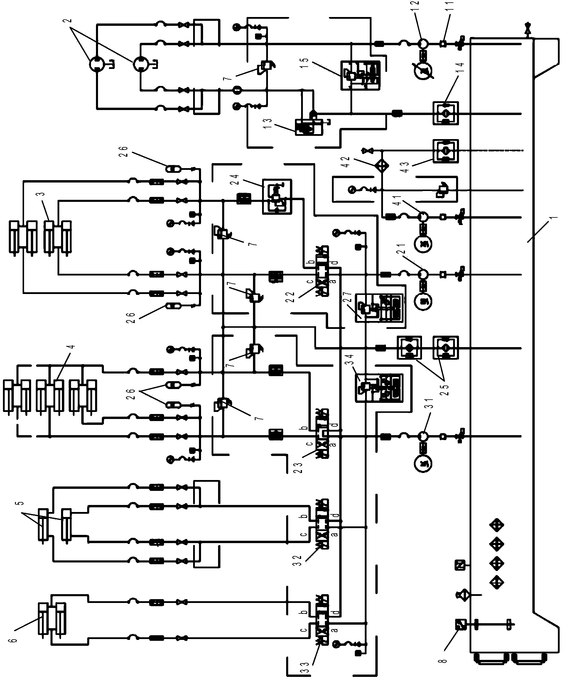
[0017] The hydraulic test system of railway tamping device of the present invention is as figure 1 As shown, it includes a fuel tank 1 and a load motor test circuit. The load motor test circuit mainly includes a shock absorber 11, a first oil suction pump 12, and a logic valve 13. The input end of the shock absorber 11 is connected to the fuel tank 1, and the output end is connected to the second One oil suction pump 12 is connected; the first oil suction pump 12 can be an internal meshing gear pump, and it is driven by a 37kw secondary frequency conversion motor, and the output end of the first oil suction pump 12 is respectively connected to the load motor of the tamping device Group 2 is connected; the input end of logic valve 13 is respectively connected with the output end of load motor group 2, and the output end of logic valve 13 is connected to oil tank 1 through the first oil return filter, and logic valve 13 is powered on and cut off when it is powered off. When the ...


PUM


Abstract

The invention discloses a hydraulic test system of a railway tamping device. The hydraulic test system of the railway tamping device comprises an oil tank, a loading motor test loop, a tamping hydraulic cylinder test loop and a turnover hydraulic cylinder test loop, wherein the loading motor test loop, the tamping hydraulic cylinder test loop and the turnover hydraulic cylinder test loop are used for detecting operation conditions of a loading motor set, a tamping hydraulic cylinder and a turnover hydraulic cylinder of the tamping device. Oil inside the oil tank can be cooled through an oil tank cooling loop. Due to the arrangement of a logical valve, when a motor of a first oil suction pump stops, power is lost for stopping, then the loading motor set stops rotating, and the motor is prevented from continuously rotating and causing air suction. Due to the arrangement of a pilot-operated type overflow valve, pressure in the loading motor test loop can be limited. A reducing valve is arranged and plays a role in pressure reduction. An energy accumulator is arranged and can play a role in shock absorption when reversing is carried out.

Description

technical field [0001] The invention belongs to a hydraulic power station, in particular to a hydraulic test system of a railway tamping device. Background technique [0002] At present, railway tamping devices are common railway maintenance equipment. During its use, it is often necessary to overhaul its load motor unit, tamping inner and outer oil cylinders, flipping inner and outer oil cylinders and other components. After the overhaul, it needs to be loaded and tested. If there is a problem, it needs to be dismantled and re-inspected, which is very inconvenient . Contents of the invention [0003] The technical problem to be solved by the present invention is to provide a hydraulic test system of a railway tamping device, which can carry out simulation tests and facilitate the maintenance of various components of the tamping device. [0004] In order to solve the problems of the technologies described above, the present invention adopts the following technical soluti...

Claims


Application Information

Patent Timeline
IPC IPC(8): F15B19/00F15B21/04F15B13/02F15B1/02
Inventor 安彩凤张杰
Owner SHANGHAI ELECTRICAL HYDRAULICS & PNEUMATICS
Why Eureka
Try Eureka