Visible light communication-based indoor positioning system and method
A visible light communication and indoor positioning technology, which is applied in positioning, radio wave measurement systems, and measurement devices, can solve the problems of large system maintenance costs, high system costs, and low accuracy, and achieve low maintenance costs, simple maintenance, and cost savings The effect of spending
- Summary
- Abstract
- Description
- Claims
- Application Information
AI Technical Summary
Problems solved by technology
Method used
Image

Examples
Embodiment 1
[0048] Visible light communication uses white light or colored light-emitting diodes to transmit information with high-speed light and dark flickering light signals that are invisible to the naked eye. It is a technology that has been used in indoor communication.
[0049] The indoor positioning system based on visible light communication in this embodiment includes a transmitter and a mobile receiver;
[0050] The transmitting end is composed of several transmitters distributed throughout the room;
[0051] The transmitter includes an LED light source for outputting the location information of the transmitter as an optical signal;
[0052] The mobile receiving end is used for receiving the optical signal, converting it into an electrical signal, and extracting position information from the electrical signal.
[0053] In a specific use process, the LED light source outputs light signals with flashing signals according to the position information that needs to be transmitted. ...
Embodiment 2
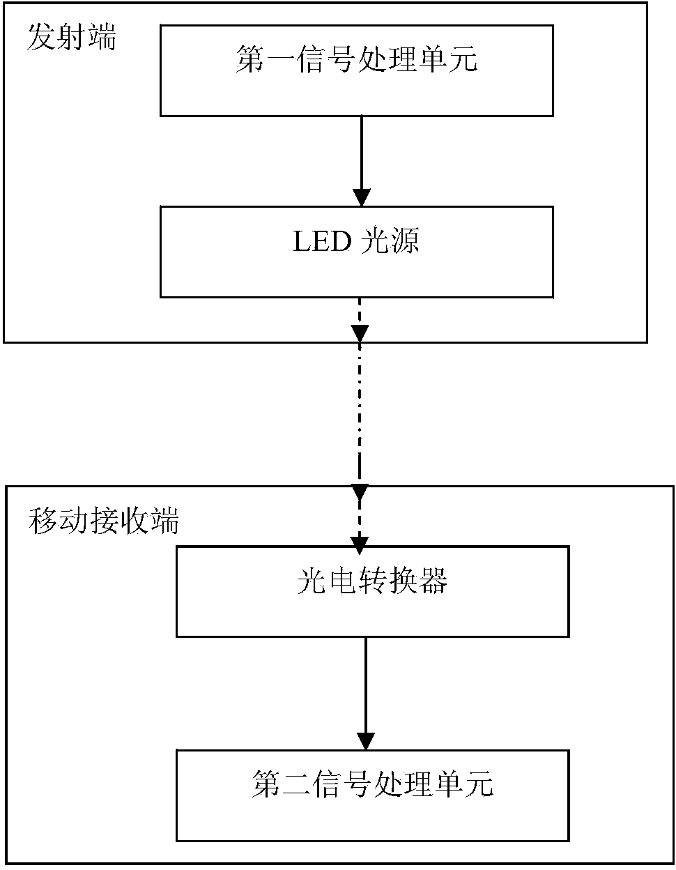
[0055] Such as figure 1 As shown, this embodiment is an indoor positioning system based on visible light communication, including a transmitter and a mobile receiver;
[0056] The transmitting end includes several transmitters distributed throughout the room; the number and position of the transmitters are set according to the needs and the preset positioning accuracy;
[0057] The transmitters include:
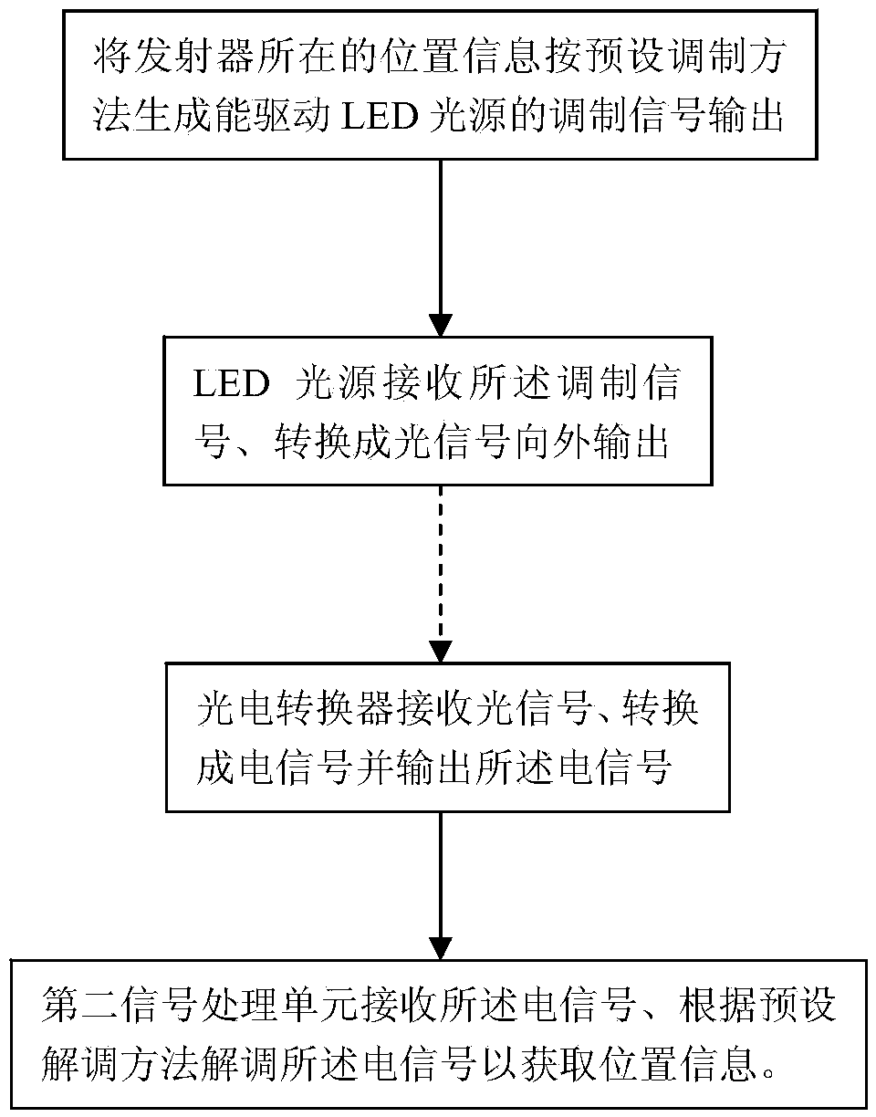
[0058] The first signal processing unit is used to generate and output the modulation signal capable of driving the LED light source from its position information; if the transmitting end is located at position A, the first signal processing unit modulates its position signal—position A according to the preset The method modulates into a modulated signal recognizable by the LED light source and outputs it to the LED light source connected thereto;
[0059] The LED light source is used to receive the modulated signal and convert it into an optical signal for output; the LED ...
Embodiment 3
[0065] The indoor positioning system based on visible light communication in this embodiment includes a transmitter and a mobile receiver;
[0066] The transmitting end is composed of several transmitters distributed throughout the room;
[0067] The transmitters include:
[0068] The first signal processing unit is used to generate and output the modulation signal capable of driving the LED light source from its location information;
[0069] LED light source, used to receive the modulation signal and convert it into a light signal for output;
[0070] The mobile receiver includes:
[0071] a photoelectric converter for receiving the optical signal and converting it into an electrical signal;
[0072] a second signal processing unit, configured to receive and demodulate the electrical signal to obtain position information;
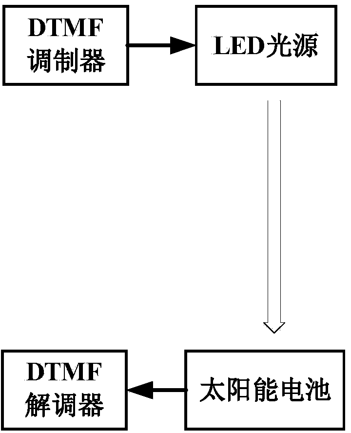
[0073] The photoelectric converter is a solar cell; the solar cell receives the light signal, absorbs the light energy carried by the light signal an...
PUM
 Abstract
Description
Claims
Application Information