Ion mobility analyzer and combination unit thereof and ion mobility analysis method

一种离子迁移率、离子迁移的技术,应用在离子迁移率分析器领域,能够解决气流快速调节、储存装置不容易实现等问题,达到提高灵敏度的效果

Active Publication Date: 2014-06-18
SHIMADZU SEISAKUSHO LTD
View PDF11 Cites 25 Cited by
  • Summary
  • Abstract
  • Description
  • Claims
  • Application Information

AI Technical Summary

Problems solved by technology

On the other hand, as the currently available low-field ion mobility storage device, it is often necessary to store ions by balancing the air flow and the electric field strength of the migration, and the air flow cannot be adjusted cheaply and quickly like the electric field, and the area is constant pressure and uniform velocity. , and precise and stable control, so high-resolution ion mobility storage devices are not easy to achieve

Method used


Image

  • Ion mobility analyzer and combination unit thereof and ion mobility analysis method
  • Ion mobility analyzer and combination unit thereof and ion mobility analysis method
  • Ion mobility analyzer and combination unit thereof and ion mobility analysis method

Examples


Embodiment 1

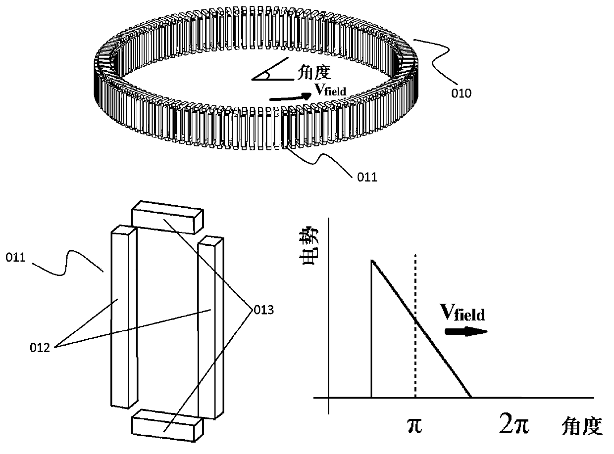
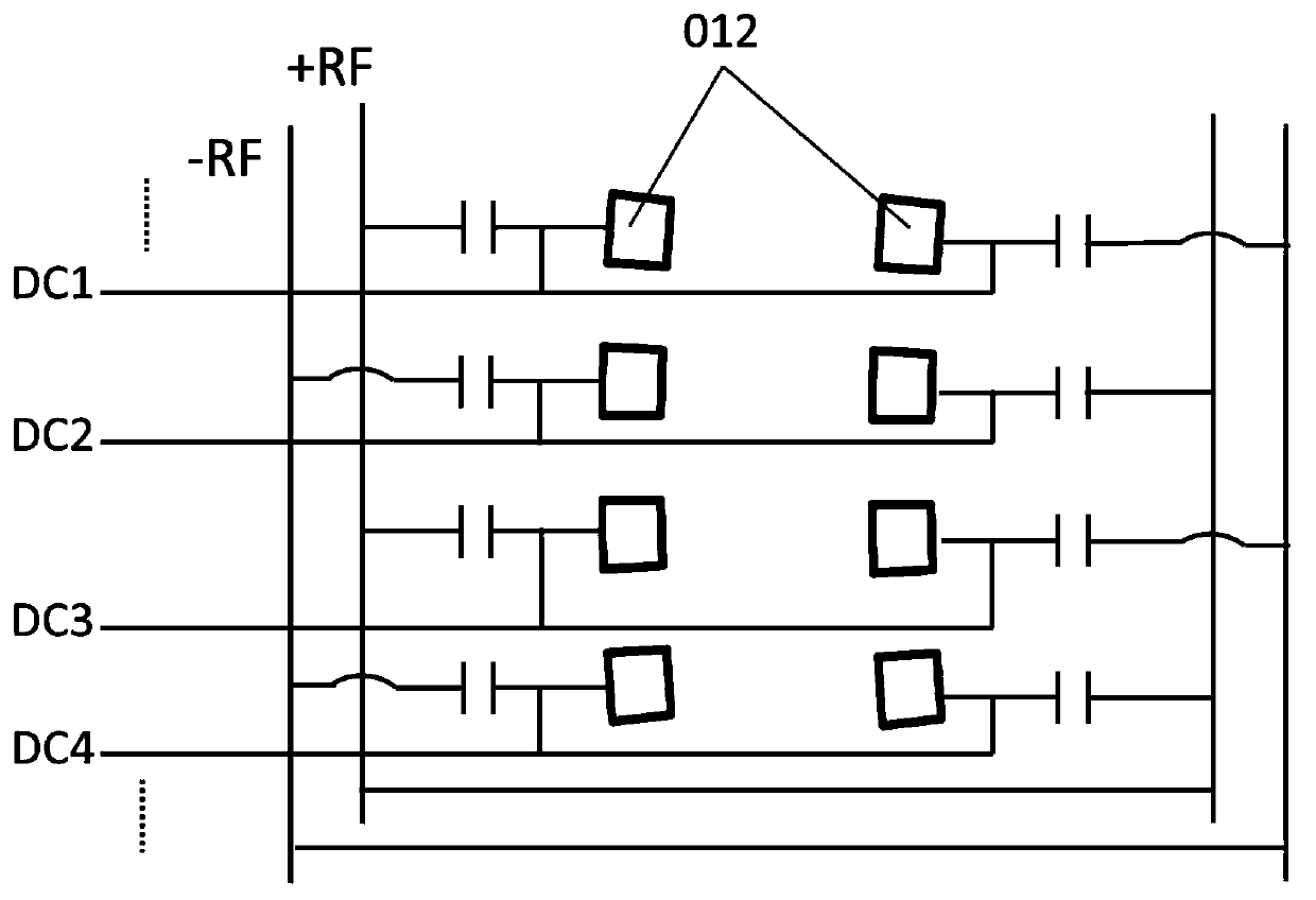
[0071] like figure 1 Shown is the best implementation structure of the ion transport device 010, the ion transport device 010 is a closed ring structure composed of a group of independently controlled electrode units 011, each independent electrode unit consists of a pair of side electrodes 012 and A pair of end cap electrodes 013 surrounds it. The ion transport device 010 is filled with a certain pressure of gas, the pressure of which is between 100Pa~3000Pa, the gas does not flow in the ion transport device 010, and basically remains in a static or near-stationary state. In order to prevent the gas inside the ion transport device 010 from being disturbed by the gas inlet and gas outlet, it should be kept as far away as possible from the gas inlet and outlet. When separating the ions entering the ion transport device 010, a linearly changing DC potential distribution is applied to the side electrodes 012 of each independent electrode unit 011, and it is rotated in the direct...

Embodiment 2

[0079] In this example, another method for generating the electric potential field for moving ions is shown. like Figure 16 As shown, among the multiple ring electrodes arranged in parallel, we sequentially add a periodic square wave waveform with a frequency of 10KHz~10MHz that switches between two levels quickly, in which, adjacent parallel electrodes such as 1601, 1602 The square waves of different phases are used to generate an electric field that binds ions in these ring electrodes. Unlike the method in the previous embodiment, in this device, we do not need to introduce a changing or instantaneous DC voltage or potential to each electrode, but achieve an average pseudo potential gradient. Wherein, the average pseudopotential voltage value Vpseudo=DV1+(1-D)V2, wherein D is the duty cycle of the high-level value V1 in the attached square wave waveform, and V2 is the low-level value.

[0080]A benefit of this design is that its pseudopotential voltage value can be preci...

Embodiment 3

[0087] As a simplification of the above scheme, it is also possible to reuse at least a part of the electrodes between different parallel structures to form a simplified ion mobility analyzer array, which is beneficial to further reduce the load capacitance and device complexity. Figure 18 A and 18B respectively give the ion mobility analyzer array structures in the form of multiplexed electrodes constructed by ring-shaped and strip-shaped electrode groups, in which 1801 and 1802 are the respective reused electrode parts of the two structures. In addition, if Figure 18 As shown in C, confinement electrodes with opposite polarities of different parallel channels, such as 1803, 1804, 1805, etc., can also be reused as confinement electrodes of adjacent ion mobility analyzers, so that the gap between the channels is only formed by the pseudopotential electric field The virtual partitions are separated to facilitate the non-destructive migration of ions between channels.

[0088...


PUM


Abstract

The invention provides an ion mobility analyzer and a combination unit thereof and an ion mobility analysis method. The ion mobility analyzer comprises an electrode system that surrounds an analysis space, and a power supply device that attaches to the electrode system an ion mobility potential field which moves along a space axis direction. In an analysis process of the mobility of ions to be tested, the ions to be tested are placed in a motion migration electric field all the time, the direction of motion of the migration field is always the same as an electric field force that the ions to be tested are subjected to in the migration field, in theory, an infinitely long migration path can be formed, ions with extremely small difference in mobility or particle size are distinguished. Through nonlinearity of the migration field, simultaneous space constraint and separation effects of ions of various mobility can be realized. The analyzer can be combined with various ion sources, detectors, mass analyzers, other ion mobility analyzers and chromatographic and spectral analysis methods, and is easy to form a large-scale analyzer array together with electrodes through a multiplexing power supply.

Description

technical field [0001] The invention relates to an ion mobility analyzer, in particular to a storage-type ion that selectively enriches ions with a specific mobility at a relative position in a certain motion analysis space to distinguish it from other ions with different mobility Mobility Analyzer. Background technique [0002] Ion mobility spectrometry is a biochemical analysis and detection device that can realize rapid screening, separation and detection of substances. In recent years, countries around the world have continuously strengthened the supervision of arms smuggling, drug trafficking, public security, homeland security and other fields. Highly selective and sensitive detection. Due to the excellent performance of ion mobility spectrometry in the above fields, people have become more and more interested in the research of ion mobility spectrometry in recent years, and its overall performance has been continuously improved. At the same time, people have used it...

Claims


Application Information

Patent Timeline
Patent Type & Authority Applications(China)
IPC IPC(8): H01J49/02H01J49/26G01N27/62G01N27/622
CPCH01J49/02G01N27/622G01N27/624H01J49/004G01N27/623H01J49/22
Inventor 蒋公羽程玉鹏张小强孙文剑
Owner SHIMADZU SEISAKUSHO LTD
Why Eureka
Try Eureka