A Harmonic Current Frequency Division Interleaved Compensation Device and Its Harmonic Current Division Frequency Given Algorithm

A harmonic current and compensation device technology, applied in harmonic reduction devices, AC networks to reduce harmonics/ripples, etc., can solve the problems of affecting filtering performance, reducing compensation performance, large loss, etc., to improve efficiency, reduce Effect of switching loss and compensation performance improvement

Inactive Publication Date: 2016-06-01
INNER MONGOLIA UNIV FOR THE NATITIES
View PDF4 Cites 0 Cited by
  • Summary
  • Abstract
  • Description
  • Claims
  • Application Information

AI Technical Summary

Problems solved by technology

PF has low cost, mature technology, and can also compensate reactive power, but there are some problems such as filtering only for specific harmonics, filter parameters affecting filtering performance, series-parallel resonance, and poor filtering effect for loads with frequently changing harmonic orders. And other issues
APF can overcome the above shortcomings, but the compensation capacity is limited by the capacity of the power device, the loss is large at high switching frequency, and the compensation performance will decrease when the capacity is large

Method used


Image

  • A Harmonic Current Frequency Division Interleaved Compensation Device and Its Harmonic Current Division Frequency Given Algorithm
  • A Harmonic Current Frequency Division Interleaved Compensation Device and Its Harmonic Current Division Frequency Given Algorithm
  • A Harmonic Current Frequency Division Interleaved Compensation Device and Its Harmonic Current Division Frequency Given Algorithm

Examples


Embodiment Construction

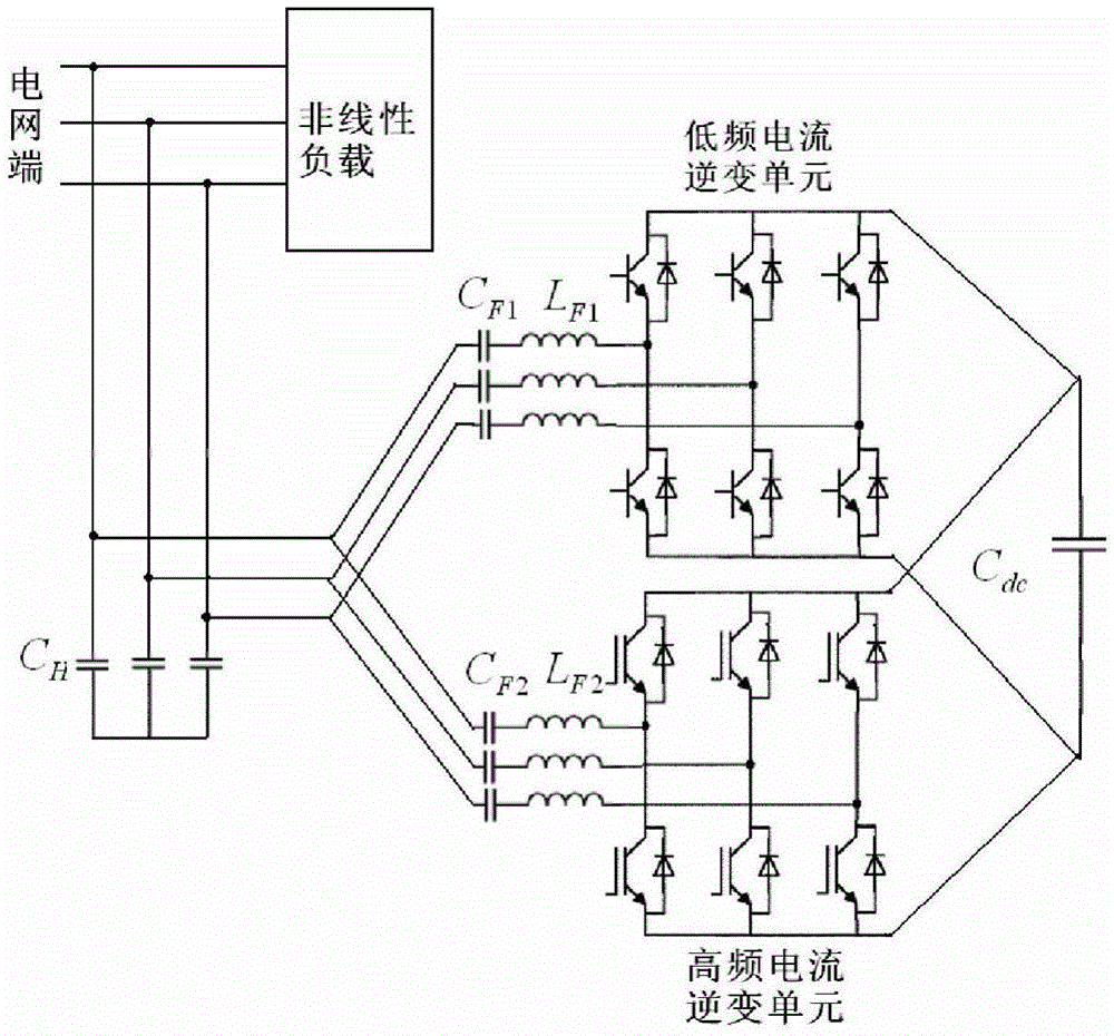
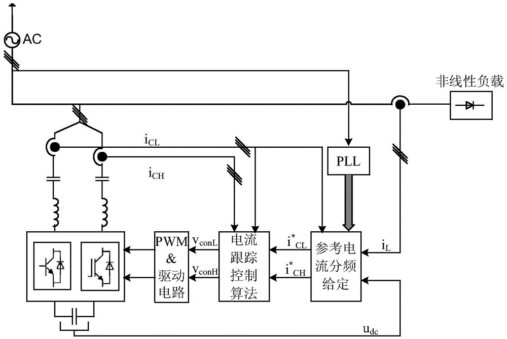
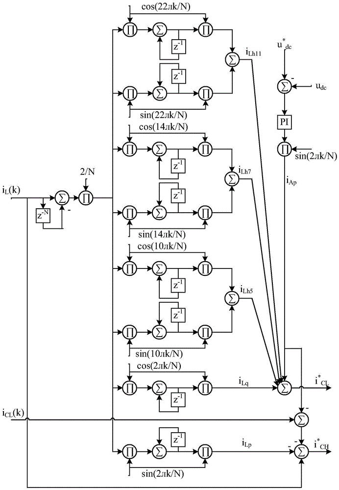
[0021] The structural diagram of this device for harmonic control of three-phase rectifier bridge plus resistive inductive load is as follows figure 2 As shown, the power supply is a 50Hz three-phase 380V AC, and the load is a nonlinear load composed of a three-phase diode rectifier bridge plus a resistive inductive load. The resistance and inductance are 26Ω and 10mH respectively. The harmonic control device consists of a phase-locked loop (PLL) module, a current and voltage sensor, a reference current frequency division given module, a current tracking control algorithm module, a PWM&drive current module and a dual inverter unit main circuit. The PLL module is composed of 74HC4046 as the core, plus an accumulation counter CD4040 and a low-pass filter. Reference current frequency division given module such as image 3 as shown, It is the low-frequency component of the compensation reference current, which is mainly composed of reactive current, 5th, 7th and 11th harmonic c...


PUM


Abstract

The invention discloses a harmonic current fractional frequency staggered compensation device and a harmonic current fractional frequency giving algorithm thereof. An active part of a main circuit of the device consists of a low-switching-frequency high-power inverter circuit unit and a high-switching-frequency low-power inverter circuit unit, wherein the low-switching-frequency high-power inverter circuit unit and the high-switching-frequency low-power inverter circuit unit are respectively responsible for generating low-frequency components and high-frequency components in harmonic reference current. The two inverter circuit units of the harmonic current compensation device share the same direct-current bus capacitor Cdc, and alternating-current sides of the two inverter circuit units are respectively and serially connected with a seventh serial harmonic branch circuit and a thirteenth serial harmonic branch circuit, then are connected with a filter capacitor and finally are connected to a power grid. A passive part formed by the serial harmonic branch circuits greatly reduces the power level of the active part. The separate giving of the reference current low-frequency components and high-frequency components is realized by adopting the harmonic current fractional frequency giving algorithm based on sliding DFT (Discrete Fourier Transform). The device effectively solves the contradictory constraint relationship among the active part components, the efficiency, the switching frequency and the compensation performance of the harmonic compensation device.

Description

technical field [0001] The invention relates to a harmonic compensation device and its harmonic current division frequency given algorithm, in particular to a high-performance and high-efficiency harmonic compensation device capable of dividing each component of harmonic current and reactive current into two groups according to frequency and performing compensation separately. wave compensation device. Background technique [0002] Medium and high voltage nonlinear loads generate a large amount of harmonic current during operation, which will bring serious power quality problems to the power grid where they are located. These problems are concentrated in the distortion and asymmetry of the load current, and the excessive distortion current will even cause the distortion of the access point voltage, and will also cause the rated operating point of other equipment to shift seriously, and the relay protection will malfunction, seriously Threats to the safe and stable operation...

Claims


Application Information

Patent Timeline
Patent Type & Authority Patents(China)
IPC IPC(8): H02J3/01
CPCY02E40/40
Inventor 韩伟周立丽
Owner INNER MONGOLIA UNIV FOR THE NATITIES
Why Eureka
Try Eureka