
Combined electric energy quality optimization device

A technology for power quality and device optimization, which is applied in harmonic reduction devices, cooling/ventilation/heating renovation, chassis/cabinet/drawer parts, etc. Line current increases and other problems, to achieve the effect of air convection heat dissipation, strengthening mechanical strength, and preventing excessive temperature

Pending Publication Date: 2022-04-26
恒一电气集团有限公司
View PDF0 Cites 0 Cited by
  • Summary
  • Abstract
  • Description
  • Claims
  • Application Information

AI Technical Summary

Problems solved by technology

[0002] Most of the electric loads in the power grid are inductive loads, such as motors. During operation, the power factor is low, the line current increases, and the power loss increases. In addition, there are electrical equipment that generate harmonics in the power grid, such as frequency converters. The transmission of harmonics in the power grid will lead to harmonic pollution and power quality problems; in other places, due to unbalanced load distribution, phase-to-phase current imbalance will occur, and the zero line current will be large, resulting in low transformer efficiency; these are problems that need to be solved urgently
Traditional power quality management equipment is bulky, complicated wiring, inconvenient to install, maintain and replace, and the effect is poor; current APF, power quality modules, SPC products, and modular products are small in size and powerful in function, which can solve the above power quality problems but there is a cost High, high power consumption, low cost performance and other issues

Method used


Image

  • Combined electric energy quality optimization device
  • Combined electric energy quality optimization device
  • Combined electric energy quality optimization device

Examples


Embodiment Construction

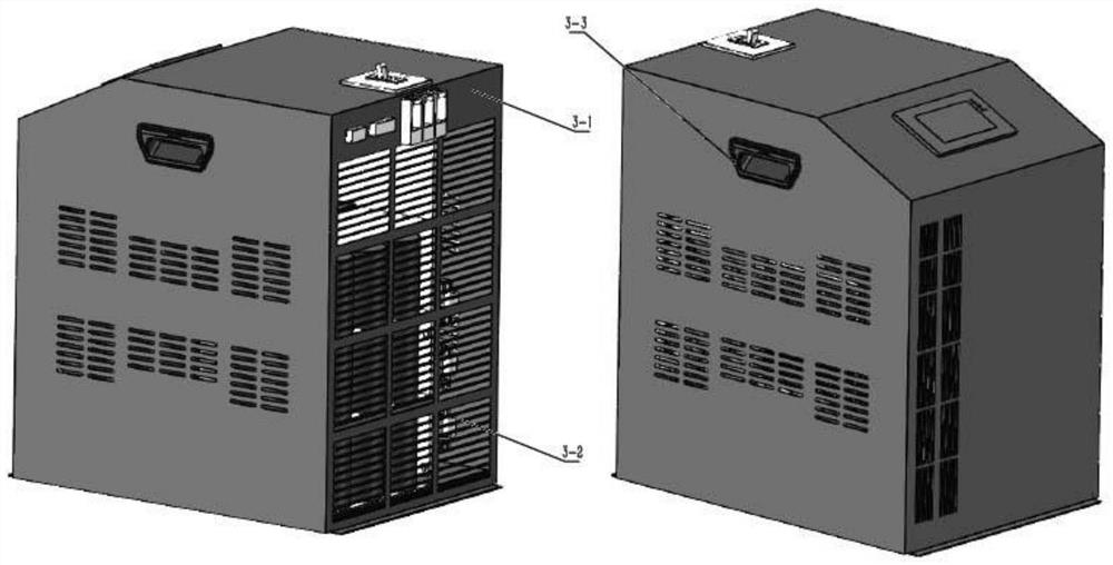
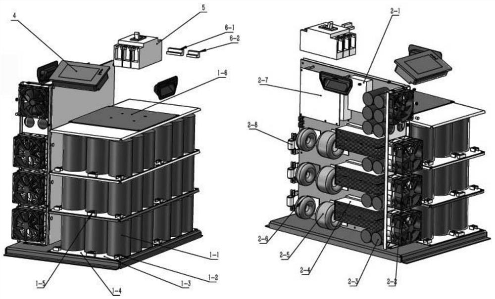
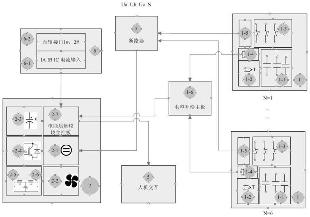
[0034] like figure 1 , figure 2 As shown, in this specific embodiment, a combined power quality optimization device, the housing 3 is composed of a housing 3-1, a base, a heat dissipation window 3-2 and a handle 3-3, and the handle 3-3 is located in the housing 3 -1 on both sides, the heat dissipation window 3-2 is located at the rear side of the housing 3-1, the base is located at the bottom of the housing 3-1, the upper end of the housing 3-1 is provided with a man-machine interface 4, and the housing 3-1 is equipped with active compensation and passive Compensation, the passive compensation unit is composed of several independent compensation units 1, circuit boards 1-4 are arranged between the independent compensation units 1, and the uppermost circuit board 1-4 is provided with a capacitor main control board 1-6, and the capacitor main control board A circuit breaker 5 is provided on one side of the board 1-6, an isolation board is provided on one side of the passive co...


PUM


Abstract

The invention discloses a combined electric energy quality optimization device, a shell is composed of a shell, a base, a heat dissipation window and handles, the handles are located at the two sides of the shell, the heat dissipation window is located at the rear side of the shell, the base is located at the bottom of the shell, the upper end of the shell is provided with a human-computer interface, and the upper end of the shell is provided with a power supply. An active compensation unit and a passive compensation unit are arranged in the shell, the passive compensation unit is composed of a plurality of independent compensation units, circuit boards are arranged among the independent compensation units, a capacitor main control board is arranged on the circuit board at the uppermost end, a circuit breaker is arranged at the upper end of one side of the capacitor main control board, an isolation board is arranged on one side of the passive compensation unit, and the capacitor main control board is arranged on the isolation board. One side of the isolation plate is provided with an electric energy quality module part; the device is small in size, light in weight, full in function, high in cost performance, convenient to expand, long in service life, small in loss, energy-saving and environment-friendly.

Description

technical field [0001] The invention relates to the technical field of electric power equipment, and more specifically relates to a combined power quality optimization device. Background technique [0002] Most of the electric loads in the power grid are inductive loads, such as motors. During operation, the power factor is low, the line current increases, and the power loss increases. In addition, there are electrical equipment that generate harmonics in the power grid, such as frequency converters. The transmission of harmonics in the power grid will lead to harmonic pollution and power quality problems; in other places, due to unbalanced load distribution, phase-to-phase current imbalance will occur, and the zero line current will be large, resulting in low transformer efficiency; these are problems that need to be solved urgently. Traditional power quality management equipment is bulky, complicated wiring, inconvenient to install, maintain and replace, and the effect is ...

Claims


Application Information

Patent Timeline
IPC IPC(8): H02J3/01H02J3/26H02J3/18H05K5/02H05K7/20
CPCH02J3/01H02J3/26H02J3/18H05K5/0247H05K7/20136Y02E40/30Y02E40/40Y02E40/50
Inventor 林佳昊林锡宏李文杰李伟郑伟
Owner 恒一电气集团有限公司
Learn More