Method for manufacturing workpieces from plate-shaped material

A technology of workpiece and plate shape, which is applied in the field of manufacturing workpieces with plate-shaped materials, can solve problems such as workpiece and scrap scraping, and achieve the effect of increased reliability and reduced work cycle

Active Publication Date: 2016-03-09
TRUMPF WERKZEUGMASCHINEN GMBH & CO KG
View PDF11 Cites 0 Cited by
  • Summary
  • Abstract
  • Description
  • Claims
  • Application Information

AI Technical Summary

Problems solved by technology

Additionally, a more complex degree of equipment is required for the construction of such laser processing machines
At the same time,

Method used


Image

  • Method for manufacturing workpieces from plate-shaped material
  • Method for manufacturing workpieces from plate-shaped material
  • Method for manufacturing workpieces from plate-shaped material

Examples


Embodiment Construction

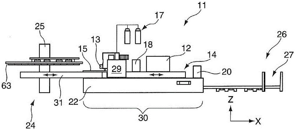
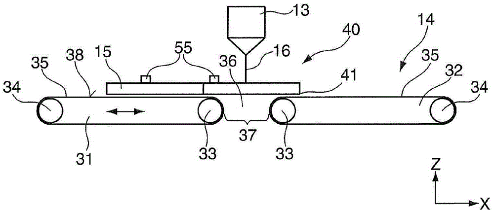
[0034] exist figure 1 , the basic structure of a machine tool 11 formed as a machining cutter is shown. Other exemplary embodiments are, for example, a laser welding machine or a combined stamping / laser cutting machine. Laser cutting machine has CO 2 A laser or solid-state laser serves as the laser beam generator 12 , which directs the laser beam via the machining head 13 onto the workpiece support 14 . Plate-shaped material 15 is arranged on this workpiece support 14 . Laser beam 16 ( image 3 ) is generated by the laser beam generator 12. The laser beam 16 from CO 2 The laser is led to the processing head 13 by means of a deflection mirror (not shown) or from a solid-state laser by means of a light guide cable (not shown). The laser beam 16 is directed onto the plate-shaped material 15 by means of focusing means arranged in the processing head 13 . The laser processing machine 11 is additionally provided with a cutting gas 17 , for example with oxygen or nitrogen. Al...


PUM

PropertyMeasurementUnit
Lengthaaaaaaaaaa

Abstract

Methods for producing workpieces from a plate-shaped material by a severing process on a machine tool having a workpiece support comprising first and second support surfaces that can be arranged relative to each other to define a cutting gap positioned below a processing area of the machine. Cuts for waste parts and/or parts of a skeleton are made in the plate-shaped material in order to produce the at least one workpiece, such that at least one last severing cut for the one or more workpieces for completely separating the one or more workpieces from the plate-shaped material remains. The waste parts and/or parts of a skeleton are removed through the cutting gap, and then the one or more workpieces are cut free from the plate-shaped material as a last severing cut in such a way that a movement of a cut workpiece over the cutting gap again is omitted.

Description

technical field [0001] The present invention relates to a method of manufacturing workpieces from plate-shaped material using a separation process in a machine tool. Background technique [0002] A 2D (two-dimensional) laser processing machine is known from patent publication WO 2007 / 137613, which laser processing machine has a workpiece support comprising a plurality of support elements arranged parallel to one another. Each of these support elements comprises bearing point ends arranged at a distance from each other, on which the plate-shaped material is supported. These points of contact between the end of the bearing point and the plate-shaped material can negatively affect the workpiece quality during the cutting process, because of scratches on the bearing side of the plate-shaped material and sticking to the end of the bearing point. Furthermore, the static support of the plate-shaped material complicates the transfer of good parts out of the machine, for which autom...

Claims


Application Information

Patent Timeline
IPC IPC(8): B23K26/08B23K26/38B23K37/04
CPCB26D3/00B23K26/0838B23K26/0869B23K26/16B23K26/38B23K37/0408B23K2101/18Y10T83/0448
Inventor P·埃佩林恩
Owner TRUMPF WERKZEUGMASCHINEN GMBH & CO KG
Why Eureka
Try Eureka