Motor control device, motor control method
A technology of motor control and speed control, applied in motor control, motor generator control, control of electromechanical brakes, etc., can solve the problems of resolver assembly error, manufacturing accuracy error, etc.
- Summary
- Abstract
- Description
- Claims
- Application Information
AI Technical Summary
Problems solved by technology
Method used
Image

Examples
no. 1 approach
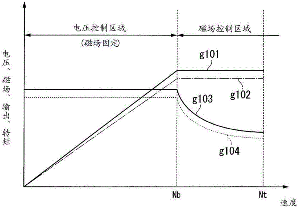
[0093] In the first embodiment, the motor is rotated in a no-load state in a field weakening control region (also referred to as a field weakening region). When the motor is rotated at high speed in the field weakening control area, the induced voltage increases and no current flows through the motor. The motor control device of the present embodiment rotates the motor at a high speed and at a constant speed in the field weakening control region, thereby flowing a d-axis current of a fixed current amount, and measures the d-axis current command value and the q-axis current command value at that time. , to calculate the offset error correction value. Hereinafter, the first embodiment will be described in detail.
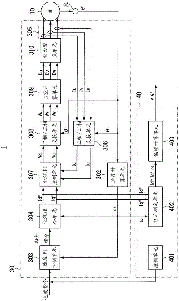
[0094] figure 1 is a control block diagram showing the motor control device of the present embodiment.
[0095] like figure 1 As shown, the motor control system 1 of this embodiment includes a resolver 20 , a motor control device 30 , and an offset correction devi...
no. 2 approach
[0224] In the second embodiment, when the motor is operated in a control region that does not generate d-axis current and does not belong to the field-weakening control region, for example, a voltage control region ( image 3 ) During low-to-medium speed rotation, the d-axis current flows by adding the d-axis current command value.
[0225] Hereinafter, the second embodiment will be described in detail.
[0226] Figure 13 is the dq coordinate system of this embodiment and the control system d c q c Control block diagram of the coordinate system.
[0227] like Figure 13 As shown, the motor control device 30b is composed of a speed calculation unit 302 , a speed PI control unit 303 , a current command unit 304a , a current PI control unit 307b , and an addition unit 331 . The controlled object 60 is composed of a first phase conversion unit 600 , a second phase conversion unit 601 , a motor voltage equation unit 602 , a torque equation unit 603 , (1 / Js) 604 , (1 / s) 605 . ...
no. 3 Embodiment approach
[0253] Next, in the third embodiment, an example of automatically adjusting the calculated offset error correction value will be described.
[0254] First, the outline of this embodiment will be described.
[0255] When the motor is rotating in a no-load state, the q-axis current Iq does not flow if the assembly error of the resolver, the signal processing delay factor caused by the motor control device, and external torque such as friction can be ignored, so the q-axis current Iq does not flow. Current command value Iq * is 0. However, when there is an assembly error of the resolver or a signal processing delay factor caused by the motor control device, the q-axis current flows, so the q-axis current command value Iq* is not zero.
[0256]Therefore, in this embodiment, the q-axis current command value when the motor rotates in a no-load state is measured, and the correction value generated by performing PI control is fed back to the motor control device so that the measured...
PUM
 Abstract
Description
Claims
Application Information