Capsule endoscopy system with ultrasonic positioning function and capsule endoscopy thereof

A technology of capsule endoscopy and ultrasound, applied in the field of medical devices, can solve problems such as relying on doctors' clinical experience, and achieve favorable and diagnostic results

Inactive Publication Date: 2014-06-25
CHONGQING JINSHAN SCI & TECH GRP
View PDF6 Cites 6 Cited by
  • Summary
  • Abstract
  • Description
  • Claims
  • Application Information

AI Technical Summary

Problems solved by technology

[0003] In view of this, this application provides a capsule endoscope system with ultrasonic positioning function and its capsule endoscope, which is used

Method used


Image

  • Capsule endoscopy system with ultrasonic positioning function and capsule endoscopy thereof
  • Capsule endoscopy system with ultrasonic positioning function and capsule endoscopy thereof
  • Capsule endoscopy system with ultrasonic positioning function and capsule endoscopy thereof

Examples


Embodiment 1

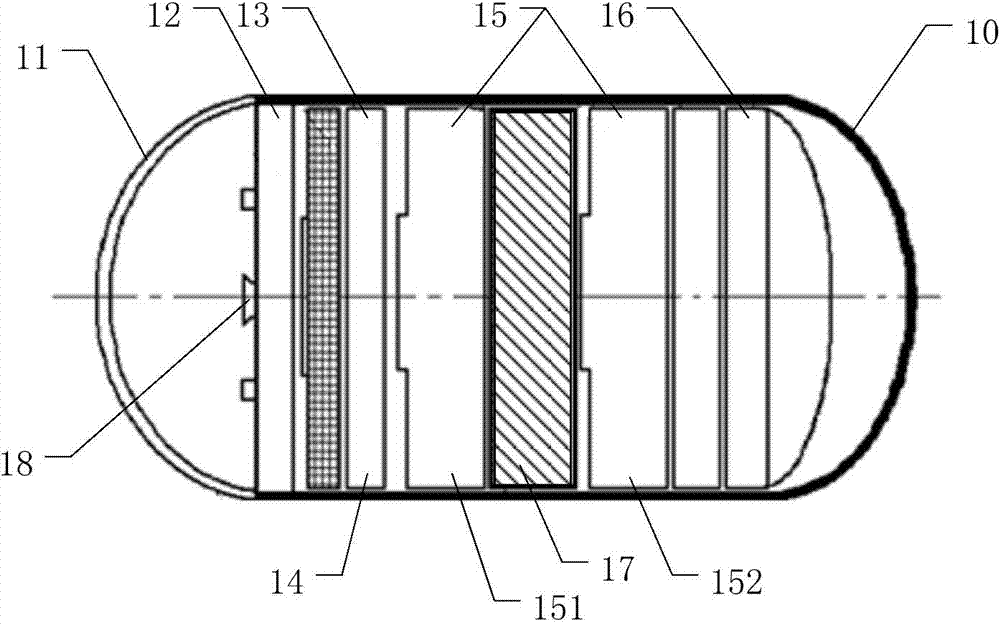
[0034] figure 1 A structural diagram of a capsule endoscope provided in an embodiment of the present application.

[0035] Such as figure 1 As shown, the capsule endoscope provided in this embodiment includes a capsule shell 10, one end of the capsule shell 10 is provided with an optical front cover 11, and an optical front cover 11 is arranged inside the capsule shell 10 in sequence from the optical front cover 11 to the other end of the capsule endoscope. A lens 12 , an image sensor 13 , an image processing module 14 , a battery module 15 and a radio frequency module 16 are arranged.

[0036] The capsule shell 10 is used to isolate the internal device from the outside, avoid body fluid contamination, and form a complete shape to facilitate administration.

[0037] The optical front cover 11 provided at one end of the capsule shell 10 is used for light transmission.

[0038] The lens 12 is arranged at a position close to the optical front cover 11 for imaging external imag...

Embodiment 2

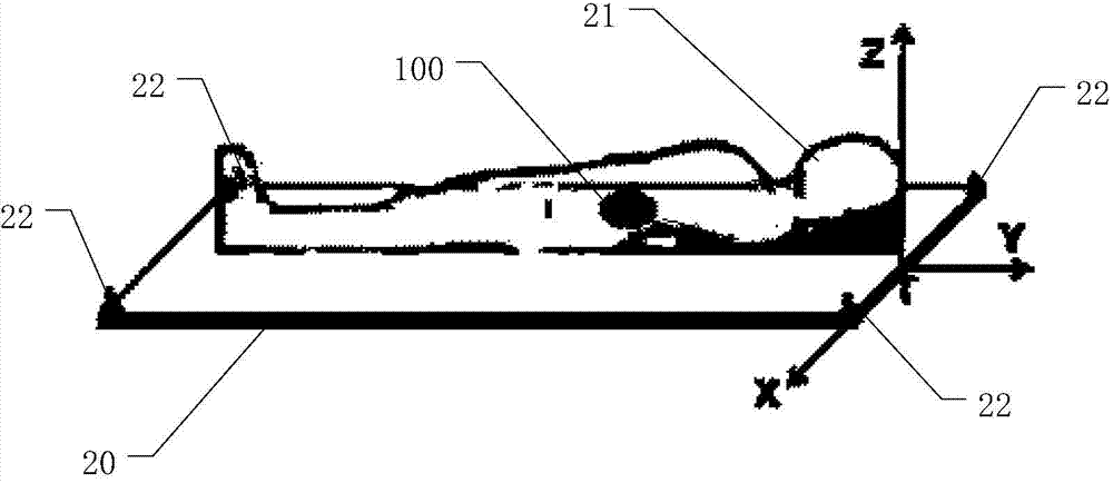
[0049] image 3 A structural diagram of a capsule endoscope system with ultrasound positioning function provided by another embodiment of the present application.

[0050] Such as image 3 As shown, the capsule endoscope system provided in this embodiment includes a positioning bed 20 and the capsule endoscope 100 provided in the previous embodiment.

[0051]The positioning bed 20 is provided with a stereotaxic coordinate system, and when the patient 21 lies on the positioning bed 20, the position of the patient 21's body relative to the stereotaxic coordinate system can be determined.

[0052] An ultrasonic array is arranged on the positioning bed 20, and the ultrasonic array includes a plurality of ultrasonic transmitters 22. In this embodiment, four ultrasonic transmitters 22 are preferably arranged on the four corners of the positioning bed 20 respectively.

[0053] After the capsule endoscope 100 is swallowed by the patient 21 lying on the positioning bed, the four ultr...


PUM


Abstract

The invention discloses a capsule endoscopy system with an ultrasonic positioning function and a capsule endoscopy of the capsule endoscopy system. The capsule endoscopy system is provided with an ultrasonic receiving module, after receiving ultrasonic signals emitted by an ultrasonic emitting array, the ultrasonic receiving module can send out beacon signals through a radio frequency unit, the beacon signals express that the ultrasonic signals are already received, and at the moment the time for ultrasonic emitted by an ultrasonic emitter to reach an ultrasonic receiver can be calculated by using the emitting time of the corresponding ultrasonic emitter in the ultrasonic emitting array and the time for generating the beacon signals, and the distance between a corresponding ultrasonic emitter and the ultrasonic receiving module can be obtained by using a sound velocity formula. The position, in the human body of a patient, of the ultrasonic receiver can be calculated in this way, so that a photo containing position information is obtained, people know which portion the photo is taken for, and a doctor does not need to depend on clinical experience too much when diagnosing the patient, which is beneficial to disease diagnosis.

Description

technical field [0001] The present application relates to the technical field of medical devices, and more specifically, to a capsule endoscope system with ultrasonic positioning function and the capsule endoscope. Background technique [0002] At present, the capsule endoscope equipment used in the medical field to diagnose the condition of the digestive tract does not have an accurate positioning function. After the patient swallows the capsule endoscope, the capsule endoscope will start to take pictures of the digestive tract according to the preset time interval, and follow the preset procedure The obtained photos are transmitted to the workstation. Since there is no location information of the photos, the doctor can only make a diagnosis based on clinical experience. However, due to factors such as different shooting angles and different lesion locations, the specific characteristics of the digestive tract vary widely, and the accuracy of disease diagnosis Too much reli...

Claims


Application Information

Patent Timeline
IPC IPC(8): A61B1/04A61B8/00
CPCG01S11/14
Inventor 张志良谢钱涛
Owner CHONGQING JINSHAN SCI & TECH GRP
Why Eureka
Try Eureka