Multi-cutter head for milling main journal of crankshaft and manufacturing process of multi-cutter head

A main journal and multi-cutter technology, which is applied in the direction of manufacturing tools, milling cutters, milling machine equipment, etc., can solve the problems of inconvenient loading and unloading of workpieces, poor crankshaft rigidity, and easy vibration, etc., to achieve convenient and ingenious adjustment, high service life, Easy to guarantee the effect of accuracy

Inactive Publication Date: 2014-06-25
XIAOGAN EZHIJIUZHOU MACHINE TOOL
View PDF7 Cites 10 Cited by
  • Summary
  • Abstract
  • Description
  • Claims
  • Application Information

AI Technical Summary

Problems solved by technology

[0003] 1. Due to the relatively large machining allowance of the crankshaft blank, it is a kind of intermittent cutting when turning the end face of the crankshaft. The impact force is particularly large during high-speed cutting, and the rigidity of the crankshaft is poor, which is easy to cause vibration
[0004] 2. When crankshaft turning, the method of multi-tool cutting with large-width forming turning tools is often used. This method solves the problem of low productivity, but it makes the workpiece bear a large cutting force during cutting, which is prone to deformation and affects machining accuracy.
[0005] 3. When turning the crankshaft of a 6-cylinder engine, an intermediate transmission method is often used, which makes it inconvenient to load and unload the workpiece. The position of the tool holder and tool for machining each gear journal needs to be adjusted separately. Therefore, when changing the variety, the readjustment workload is large
[0006] 4. At present, in the crankshaft manufacturing and processing, some manufacturers use imported cutterheads to process domestic blanks, which have problems such as low efficiency, unsatisfactory chip removal, high cutting temperature, and large vibration.

Method used


Image

  • Multi-cutter head for milling main journal of crankshaft and manufacturing process of multi-cutter head
  • Multi-cutter head for milling main journal of crankshaft and manufacturing process of multi-cutter head
  • Multi-cutter head for milling main journal of crankshaft and manufacturing process of multi-cutter head

Examples


Embodiment 1

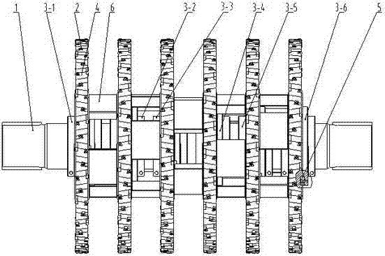
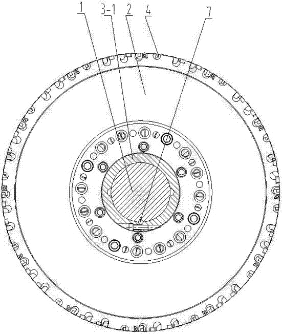
[0037] refer to Figure 1-Figure 7 , taking the processing of a six-cylinder crankshaft as an example, the present invention includes a main shaft 1, 6 identical cutterheads 2 and 6 cutterhead seats 3-1, 3-2, 3-3, 3-4, 3 with specific design angles -5, 3-6, 12 groups of blades 4 are installed on the circumferential surface of each cutterhead 2, each group includes 6 blades, the positions of the 12 groups of blades 4 relative to the cutterhead 2 are consistent, and the blades with the same function are evenly distributed on the cutterhead Each blade is set at a different busbar position, and the six cutterheads 2 are fixed to the six cutterhead seats 3-1, 3-2, 3-3, Between 3-4, 3-5, and 3-6, six cutterhead seats 3 are locked on the main shaft 1 through round keys and locking screws, and a detachable adjustment pad is set between the cutterhead 2 and the cutterhead 2 6. The cutter head 2 is provided with a plurality of round holes 10, and the adjustment block 6 is provided with...

Embodiment 2

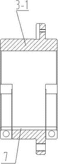
[0040] refer to figure 2 The difference between embodiment 2 and embodiment 1 is that the cutter head seat 3 is fixed on the circumferential direction of the main shaft 1 through the round key 7 and the V-shaped groove 8 of the main shaft 1, so that the cutter head Dislocation distribution of the upper blade, uniform force and small vibration during milling, easy to ensure accuracy.

[0041] The concrete steps and process of making this invention are:

[0042] The first step is to select alloy tool steel to process and manufacture multiple cutterhead seats according to the design drawings, respectively to ensure the end face key angle of each specific design, to ensure the corresponding dimensional accuracy, shape tolerance and surface roughness requirements, and to quench and temper.

[0043] The second step is to process and manufacture multiple cutterheads (corresponding to the number of crankshaft main journals) according to the design drawings, to ensure the correspondi...


PUM


Abstract

The invention relates to the field of machining and manufacturing of crankshafts and in particular relates to a multi-cutter head for milling a main journal of a crankshaft and a manufacturing process of the multi-cutter head. The multi-cutter head comprises a spindle, cutter head bodies and cutter head seats, wherein multiple identical cutter head bodies provided with multiple blades are fixed on multiple cutter head seats through which cutter teeth of the cutter head bodies are staggered through straight end-face keys and the multiple cutter head seats have certain angle; the multiple cutter head seats are and connected and locked onto the spindle through round keys; a detachable adjusting cushion block is arranged between every two cutter head bodies. According to the multi-cutter head, the cutter head bodies are connected with the cutter head seats, cutter teeth of each cutter head body are staggered, the distance between every two cutter head bodies can be adjusted by the rapidly detached adjusting cushion block arranged between the cutter head bodies, thus the multi-cutter head is convenient and ingenious, rigidity of serially cutter groups and the cutter head bodies are guaranteed from the structure, each cutter head is uniform in stress and small in vibration during milling, interrupted cut is met, the production efficiency is high, the machining efficiency is high, the precision is easily guaranteed, and the multi-cutter head is long in service life.

Description

technical field [0001] The invention relates to the field of mechanical processing and manufacturing of crankshafts, in particular to a multi-cutter disc for milling crankshaft main journals and a manufacturing process thereof. Background technique [0002] The traditional crankshaft rough turning manufacturing has the following disadvantages: [0003] 1. Due to the relatively large machining allowance of the crankshaft blank, turning the end face of the crankshaft is a kind of intermittent cutting. The impact force is particularly large during high-speed cutting, and the rigidity of the crankshaft is poor, which is easy to cause vibration. [0004] 2. When crankshaft turning, the method of multi-tool cutting with large-width forming turning tools is often used. This method solves the problem of low productivity, but it makes the workpiece bear a large cutting force during cutting, which is prone to deformation and affects machining accuracy. . [0005] 3. When turning the...

Claims


Application Information

Patent Timeline
Patent Type & Authority Applications(China)
IPC IPC(8): B23C5/08B23C5/20B23P15/34
Inventor 陈继红林文学彭文烨余志凌龙涛龚善林
Owner XIAOGAN EZHIJIUZHOU MACHINE TOOL
Why Eureka
Try Eureka