Precise chamfering device for optical component

A technology of optical components and chamfering, which is applied in the direction of grinding/polishing equipment, metal processing equipment, grinding machine parts, etc. How to ensure the consistent amount of chamfering of optical components and other issues, to achieve the effect of low technology and proficiency requirements, high consistency, and good chamfering consistency

Inactive Publication Date: 2014-06-25
郑凤金
View PDF9 Cites 1 Cited by
  • Summary
  • Abstract
  • Description
  • Claims
  • Application Information

AI Technical Summary

Problems solved by technology

[0002] At present, there is no precision chamfering equipment for optical components that can be adjusted and the chamfering amount can be digitally displayed. The traditional chamfering of optical components relies on the operator to hold the optical part on a flat grinding disc and measure the chamfering amount while grinding. The method to control the amount of chamfering, the traditional method is highly dependent on the skills and proficiency of the operator, and it is difficult to manually control the amount of optical chamfering, it is basically impossible to ensure that the amount of chamfering of different optical components is consistent, with the optical module based on With the continuous development of automatic assembly of machine vision technology and the continuous increase of labor costs, the chamfering of optical parts is increasingly required to have high quality, that is, the amount of chamfering should be accurate and the consistency of individual chamfering should be good. This technology is based on the chamfering of optical parts The small feature has completely changed the traditional way of chamfering with a flat grinding disc. It cleverly uses the electroplated emery arc surface to grind the right-angled edges of optical components. The relative movement of the inclined-plane slider adjusts the distance between the chamfering jaw and the grinding shaft surface. The relative movement distance of the inclined-plane slider is converted by AD and calculated by the microprogram controller to obtain an accurate chamfering value, which is displayed in real time through the digital tube. out, allowing for precise control and display of optic bevels

Method used


Image

  • Precise chamfering device for optical component
  • Precise chamfering device for optical component

Examples


Embodiment Construction

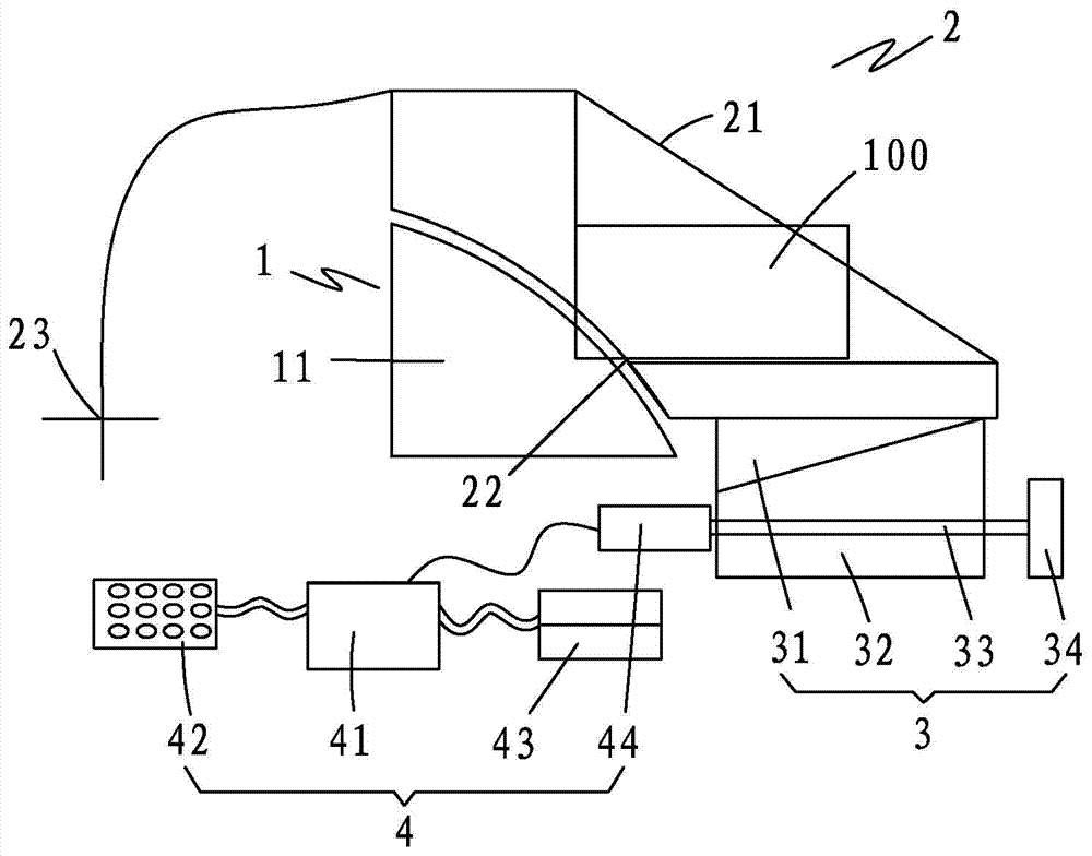
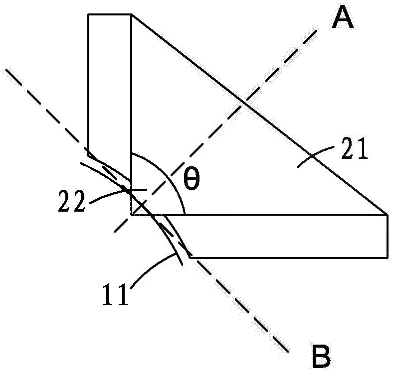
[0014] see figure 1 and figure 2 As shown, the optical element precision chamfering equipment of the present invention includes a grinding device 1, a chamfering jaw device 2, a chamfering amount adjusting device 3 and a control display device 4; the grinding device 1 includes a grinding shaft 11, The chamfering jaw device 2 has an angular clamping groove 21, a chamfering station opening 22 and a rotation center 23 deviated from the axis of the grinding shaft 11, and the chamfering station opening 22 is located in the angular clamping groove 21 The inner corner of the inner corner; the grinding shaft 11 is adjacent to the chamfering station opening 22 and is located between the angular clamp groove 21 and the center of rotation 23, and the inner corner of the angular clamp groove 21 The angle bisector A is perpendicular to the grinding shaft outer circle tangent B passing through the angle bisector; the chamfering adjustment device 3 is connected to the chamfering jaw device...


PUM


Abstract

The invention provides a precise chamfering device for an optical component. The precise chamfering device comprises a grinding device, a chamfering clamping device, a chamfering amount adjusting device and a control displaying device. The grinding device comprises a grinding shaft. The chamfering clamping device is provided with an angular clamping groove, a chamfering station opening and a rotating center deviating from the axis of the grinding shaft, and the chamfering station opening is located in the corner position of the inner end of the angular clamping groove. The grinding shaft is adjacent to the chamfering station opening and is located between the angular clamping groove and the rotating center. The angular bisector of the corner position of the inner end of the angular clamping groove is perpendicular to the tangent, passing through the angular bisector, of an outer circle of the grinding shaft. The chamfering amount adjusting device is connected with the chamfering clamping device and adjusts the angular clamping groove to rotate around the rotating center. The control displaying device is respectively connected with the chamfering amount adjusting device and the grinding device. The precise chamfering device can visually measure the chamfering amount in real time, the chamfering precision and consistency can be improved, and the operating requirement can be lowered.

Description

technical field [0001] The invention relates to a precision chamfering equipment for optical elements. Background technique [0002] At present, there is no precision chamfering equipment for optical components that can be adjusted and the chamfering amount can be digitally displayed. The traditional chamfering of optical components relies on the operator to hold the optical part on a flat grinding disc and measure the chamfering amount while grinding. The method to control the amount of chamfering, the traditional method is highly dependent on the skills and proficiency of the operator, and it is difficult to manually control the amount of optical chamfering, it is basically impossible to ensure that the amount of chamfering of different optical components is consistent, with the optical module based on With the continuous development of automatic assembly of machine vision technology and the continuous increase of labor costs, the chamfering of optical parts is increasingl...

Claims


Application Information

Patent Timeline
Patent Type & Authority Applications(China)
IPC IPC(8): B24B9/14B24B51/00
CPCB24B9/148B24B51/00
Inventor 郑凤金
Owner 郑凤金
Why Eureka
Try Eureka