Four side return air side directional air supply air source heat pump system

A heat pump system and side return technology, which is applied in the operation mode of the machine, the combination of heating and cooling, lighting and heating equipment, etc., can solve the problems of deteriorating the working environment of the air source host, inability to save energy, and reducing work efficiency. Achieve the effect of reducing material consumption, compact structure and improving efficiency

Active Publication Date: 2016-05-11
郑州瑞邦精密机械制造有限公司
View PDF11 Cites 0 Cited by
  • Summary
  • Abstract
  • Description
  • Claims
  • Application Information

AI Technical Summary

Problems solved by technology

Seriously deteriorated the working environment of the wind source host
The working efficiency of the main engine is much lower than the working efficiency under the actual weather conditions, and it cannot run in an energy-saving manner

Method used


Image

  • Four side return air side directional air supply air source heat pump system
  • Four side return air side directional air supply air source heat pump system
  • Four side return air side directional air supply air source heat pump system

Examples


Embodiment 1

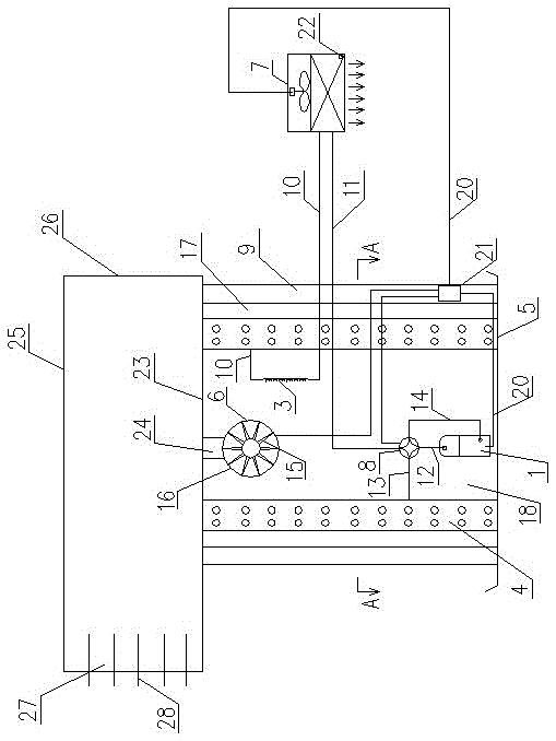
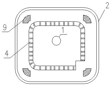
[0022] The air source heat pump system of the four side air return and side directional air supply in this embodiment is as follows: figure 1 As shown, it includes an outdoor unit and an indoor unit. The outdoor unit is divided into an outer chamber 17 and an inner chamber 18 by a heat exchanger 4. The outer chamber 17 is surrounded by a part of the heat exchanger 4 and the shell 2. The outer chamber 17 communicates with the atmosphere. , the inner chamber 18 is composed of a heat exchanger 4, a base plate 5, an edge-sealing cover plate 31 connecting the two ends of the heat exchanger 4, a centrifugal fan 6, and a volute plate 23 for installing the centrifugal fan 6, and the centrifugal fan 6 is installed inside In the chamber 18, the centrifugal fan 6 is composed of a volute 16, blades and its motor assembly 15. The static pressure chamber 26 communicates with the inner chamber 18, and the outer side of the static pressure chamber is provided with a main engine air outlet 27, ...

Embodiment 2

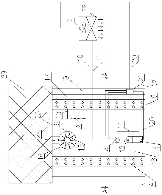
[0025]In Embodiment 2, the guide vane assembly is changed to an anti-foreign matter intrusion net 29 at the air outlet, and the others are the same as Embodiment 1.

Embodiment 3

[0027] In embodiment 3, the air outlet is changed to a plurality of circular jet holes 30, and the others are the same as in embodiment 1.

[0028] The use method of the present invention is as follows: before use, turn on the power supply, set the operation mode and temperature parameters. At this time, the whole system will automatically work according to the setting to realize energy-saving operation.

[0029] The indoor part of the present invention can also be in the form of conventional fan coil units, air duct machines, floor heating and cooling tube bundles, floor heating tube bundles and indoor surface coolers for cooling and heating supply, etc. The change of the form of the indoor terminal, the change of the layout of the outdoor cavity, the air outlet of the main engine from one side or multiple sides, the change of the form of the air outlet, the change of the form and length of the guide vane, etc. are all covered by the present invention. Technical coverage.


PUM


Abstract

Disclosed is an air source heat pump system with four air return side faces directionally supplying air. A centrifugal fan replaces an axial flow fan. A cavity is defined by a surface air cooler and a lower base plate. The centrifugal fan is installed on the upper portion of the cavity defined by the surface air cooler. A volute, blades and a cover plate of the centrifugal fan, the surface air cooler and the lower base plate form a static pressure air return cavity, an air outlet and the cover plate of the centrifugal fan, and an upper cover plate of a unit form a larger cavity used as an air outlet static pressure box of the centrifugal fan, an air outlet is formed in the side face of the static pressure box, a flow guide blade or a circular jet flow hole is added in the air outlet, and an air outlet of a main machine is moved out to be far away from the main machine. By the adoption of the scheme, the condensing temperature of the system during cooling reduces 4 DEG C to 11 DEG C, and the energy efficiency ratio of the main machine is 10% higher than that in a traditional mode; the evaporation temperature of the heat pump system during heating rises more than 5 DEG C to 8 DEG C, and the energy efficiency ratio of the main machine is 7% higher than that in a traditional mode; the air source heat pump system with the four air return side faces directionally supplying air has higher promotional value.

Description

technical field [0001] The invention relates to a cooling and heating device. Background technique [0002] my country has become the world's largest manufacturer of small air source heat pumps and the largest user country. The safety, reliability and stability of air source heat pumps are known and accepted by everyone. However, the air source heat pump is greatly affected by the ambient temperature. In the north, the outdoor temperature is lower than -5°C for a long time in winter and higher than 35°C in summer. At this time, the energy efficiency ratio of the air source heat pump will be low. In recent years, people have adopted large-scale The water source heat pump system solves the problem of heating and cooling. However, due to the limitation of geological conditions in most areas of my country, the groundwater stock is limited, and the recharge of the extracted groundwater is difficult. The application of large water source heat pumps is greatly restricted. Therefore,...

Claims


Application Information

Patent Timeline
Patent Type & Authority Patents(China)
IPC IPC(8): F25B29/00
Inventor 陈万仁梁年良孙长江何欣曹双俊张亮
Owner 郑州瑞邦精密机械制造有限公司
Why Eureka
Try Eureka