Probe bracket for ultrasonic artificial detection of steel plate

A technology of manual detection and probe support, applied in the field of probe support, can solve problems such as stability affecting the accuracy of detection results, reduce the service life of probes, and reduce labor intensity, so as to avoid misjudgment or missed detection of defects and reduce production costs. Maintain and increase the effect of the coupling effect

Inactive Publication Date: 2014-06-25
JIGANG GRP
View PDF11 Cites 4 Cited by
  • Summary
  • Abstract
  • Description
  • Claims
  • Application Information

AI Technical Summary

Problems solved by technology

The diameter of the probe used in the ultrasonic inspection of the steel plate is less than 25mm, and the surface area of ​​the steel plate is relatively large, so scanning the steel plate is labor-intensive and the detection efficiency is very low
In the process of ultrasonic testing of steel plates, water is used as a coupling agent between the steel plate and the probe to remove the air between the two. Manual testing requires the operator to exert continuous and stable force on the probe, and uneven force will affect the coupling effect and defect signal The stability of the test will affect the accuracy of the test results
In addition, the surface of the steel plate is relatively rough. Excessive force by the operator during manual inspection will accelerate the wear of the plexiglass of the probe and reduce the service life of the probe; if the force is too small, the detection sensitivity will be reduced, and the reflected echo will also be greatly reduced.
[0004]Some domestic manufacturers use automatic flaw detection equipment to conduct ultrasonic testing on steel plates. Compared with manual testing, automatic testing reduces labor intensity and the test results are stable. The probe is expensive, and the steel plate is not allowed to have more than the specified curvature or wave, and the steel plate is often scratched by the probe, which affects the timely delivery of the product

Method used


Image

  • Probe bracket for ultrasonic artificial detection of steel plate

Examples


Embodiment Construction

[0019] In order to clearly illustrate the technical characteristics of this solution, the following will describe this solution through specific implementation modes and in conjunction with the accompanying drawings.

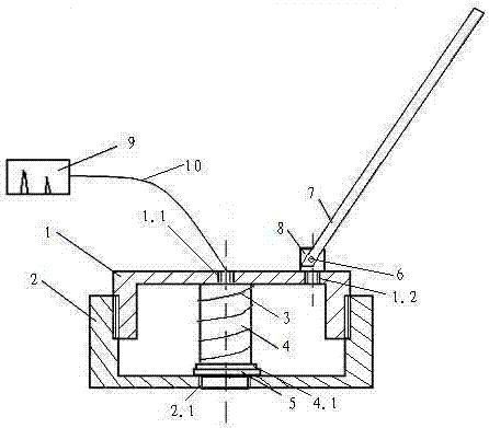
[0020] As shown in the figure: a probe bracket for ultrasonic manual detection of steel plates, which includes an upper support 1 and a base 2, the upper support 1 and the base 2 are threaded, and a Probe 4, the probe 4 is provided with a shoulder 4.1, the upper support 1 is provided with a center hole I1.1, the base 2 is provided with a center hole II2.1, the upper end of the probe 4 and the center The hole I1.1 is matched and connected to the ultrasonic detector 9 through the wire 10, the lower end of the probe 4 is matched with the center hole II2.1, and a spring 3 is arranged on the periphery of the probe 4, and the spring 3 is located between the shoulder 4.1 Between the upper supports 1 , a tie rod 7 is fixedly connected to the upper supports 1 . The prob...


PUM

PropertyMeasurementUnit
lengthaaaaaaaaaa

Abstract

The invention relates to a probe bracket for the ultrasonic artificial detection of a steel plate. The probe bracket comprises a shell, a stress application part and a displacement part, wherein the shell comprises a base and an upper support seat connected with the base by screw thread; the base and the upper support seat are respectively provided with a center hole used for arranging a probe; the upper end of the probe is connected with an ultrasonic detector by a lead; the stress application part is a spring arranged between the upper support seat and the probe; the displacement part comprises a pull rod connected with the upper support seat. The probe bracket for the ultrasonic artificial detection of the steel plate mainly comprises the upper support seat, the base, the spring and the pull rod, so that the manufacturing cost is low and maintenance is not needed; the upper support seat, the base and the spring are assembled, so that the stress applied to the probe is uniform, stable and continuous under the action of the elastic force of the spring; the distance between the lower end surface of the probe and the steel plate is stable, so that the coupling effect is improved, the detection sensitivity and the reflection echo are in accordance with the standard requirements, and defect misjudgement or missing detection can be avoided.

Description

technical field [0001] The invention relates to the field of nondestructive testing equipment, in particular to a probe bracket used in the process of ultrasonic manual testing of steel plates. Background technique [0002] With the rapid development of non-destructive testing technology, ultrasonic testing has been widely used in pressure vessels, bridges, boiler manufacturing, oil and gas transmission pipelines, power plants, nuclear power plants and other fields. Since the steel plate is rolled from a slab, its defects are mainly parallel to the plate Therefore, the longitudinal wave straight probe method is mainly used in the ultrasonic testing of steel plates. At present, there are two main methods of steel plate detection in general: manual detection and automatic detection. [0003] Manual detection requires the operator to hold an ultrasonic flaw detector in one hand, and the other hand-held probe to scan the surface of the steel plate along the direction perpendicu...

Claims


Application Information

Patent Timeline
Patent Type & Authority Applications(China)
IPC IPC(8): G01N29/22G01N29/04
Inventor 刘强侯文科李雪东柳彩枫司春杰黄伟东李金霞袁婷婷
Owner JIGANG GRP
Why Eureka
Try Eureka